Toyota Yaris: Shift And Select Lever Shaft / Disassembly
DISASSEMBLY
PROCEDURE
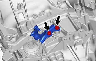
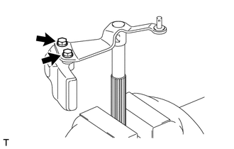
1. REMOVE SELECTING BELL CRANK ASSEMBLY
| (a) Remove the 2 bolts and selecting bell crank assembly from the manual transmission case. |
|
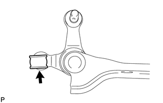
2. REMOVE CONTROL SHIFT LEVER BUSHING
| (a) Remove the control shift lever bushing from the selecting bell crank assembly. |
|
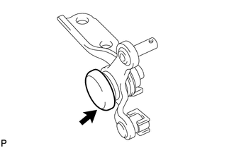
3. REMOVE NO. 1 SELECTING BELL CRANK DUST COVER
| (a) Remove the No. 1 selecting bell crank dust cover from the selecting bell crank assembly. |
|
4. REMOVE BACK-UP LIGHT SWITCH ASSEMBLY
Click here

5. REMOVE NEUTRAL POSITION SWITCH
Click here

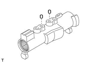
6. REMOVE NO. 1 LOCK BALL ASSEMBLY
Click here

7. REMOVE NO. 2 LOCK BALL ASSEMBLY
Click here

8. REMOVE SHIFT GATE PIN
Click here

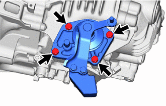
9. REMOVE SHIFT AND SELECT LEVER ASSEMBLY
| (a) Remove the 4 bolts and shift and select lever assembly from the manual transmission case. |
|
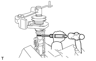
10. REMOVE NO. 1 SHIFT LEVER INNER
| (a) Using a pin punch and hammer, remove the slotted spring pin from the No. 1 shift lever inner. |
|
| (b) Remove the No. 1 shift lever inner and shift interlock plate from the shift and select lever shaft. |
|
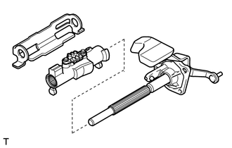
11. REMOVE SHIFT AND SELECT LEVER SHAFT
| (a) Remove the control shaft cover and the shift and select lever boot from the shift and select lever shaft. |
|
12. REMOVE SHIFT GATE PLATE
| (a) Remove the 2 bolts and shift gate plate from the No. 1 shift lever inner. |
|
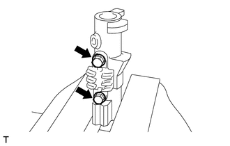
13. REMOVE PIN
| (a) Remove the 2 pins from the No. 1 shift lever inner. |
|
14. REMOVE SHIFT LEVER DAMPER
| (a) Remove the 2 bolts and shift lever damper from the shift lever shaft. |
|
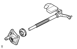
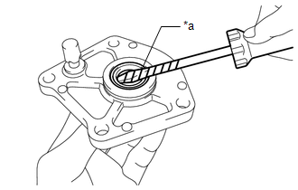
15. REMOVE CONTROL SHAFT COVER OIL SEAL
| (a) Using a screwdriver with its tip wrapped with protective tape, remove the control shaft cover oil seal from the control shaft cover. |
|
 Components
COMPONENTS ILLUSTRATION
*1 SHIFT AND SELECT LEVER ASSEMBLY *2 NO. 1 SELECTING BELL CRANK DUST COVER *3 SELECTING BELL CRANK ASSEMBLY *4 CONTROL SHIFT LEVER BUSHING *5 SHIFT GATE PIN *6 NO...
 Reassembly
REASSEMBLY PROCEDURE 1. INSTALL CONTROL SHAFT COVER OIL SEAL (a) Using SST and a hammer, install a control shaft cover oil seal to the control shaft cover...
Other information:
Toyota Yaris XP210 (2020-2026) Reapir and Service Manual: Transmission Fluid Temperature Sensor "A" Circuit Short To Ground (P071011)
DESCRIPTION The manual transaxle oil temperature sensor (temperature sensor) installed inside the manual transaxle assembly detects the temperature of the fluid in the transaxle and outputs signals to the ECM according to the fluid temperature. DTC No...
Toyota Yaris XP210 (2020-2026) Reapir and Service Manual: Data List / Active Test
DATA LIST / ACTIVE TEST DATA LIST NOTICE: In the following table, the values listed under "Normal Condition" are reference values. Do not depend solely on these reference values when deciding whether a part is faulty or not. HINT: Using the GTS to read the Data List allows the values or states of switches, sensors, actuators and other items to be read without removing any parts...
Categories
- Manuals Home
- Toyota Yaris Owners Manual
- Toyota Yaris Service Manual
- Engine & Hybrid System
- Auto Lock/Unlock Function
- G16e-gts (engine Mechanical)
- New on site
- Most important about car
Fuel Gauge
The fuel gauge shows approximately how much fuel is remaining in the tank when the ignition is switched ON. We recommend keeping the tank over 1/4 full.
