Toyota Yaris: Shift And Select Lever Shaft / Components
COMPONENTS
ILLUSTRATION
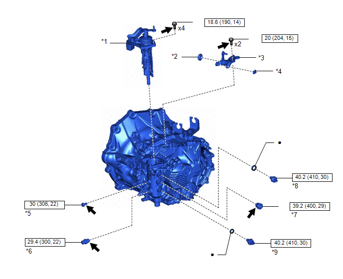
| *1 | SHIFT AND SELECT LEVER ASSEMBLY | *2 | NO. 1 SELECTING BELL CRANK DUST COVER |
| *3 | SELECTING BELL CRANK ASSEMBLY | *4 | CONTROL SHIFT LEVER BUSHING |
| *5 | SHIFT GATE PIN | *6 | NO. 2 LOCK BALL ASSEMBLY |
| *7 | NO. 1 LOCK BALL ASSEMBLY | *8 | BACK-UP LIGHT SWITCH ASSEMBLY |
| *9 | PARK/NEUTRAL POSITION SWITCH ASSEBMLY | - | - |
 | N*m (kgf*cm, ft.*lbf): Specified torque | ● | Non-reusable part |
 | Adhesive 1344 | ★ | Precoated part |
ILLUSTRATION
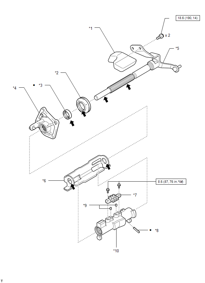
| *1 | SHIFT LEVER DAMPER | *2 | SHIFT AND SELECT LEVER BOOT |
| *3 | CONTROL SHAFT COVER OIL SEAL | *4 | CONTROL SHAFT COVER |
| *5 | SHIFT AND SELECT LEVER SHAFT | *6 | SHIFT INTERLOCK PLATE |
| *7 | SHIFT GATE PLATE | *8 | SLOTTED SPRING PIN |
| *9 | PIN | *10 | NO. 1 SHIFT LEVER INNER |
 | N*m (kgf*cm, ft.*lbf): Specified torque | ★ | Precoated part |
| ● | Non-reusable part |
 | MP grease |

 Disassembly
DISASSEMBLY PROCEDURE 1. REMOVE SELECTING BELL CRANK ASSEMBLY (a) Remove the 2 bolts and selecting bell crank assembly from the manual transmission case...
Other information:
Toyota Yaris XP210 (2020-2026) Reapir and Service Manual: Driver Frontal Stage 1 Deployment Control Circuit Resistance Below Threshold (B00011A)
DESCRIPTION DTC No. Detection Item DTC Detection Condition Trouble Area Warning Indicate Test Mode / Check Mode B00011A Driver Frontal Stage 1 Deployment Control Circuit Resistance Below Threshold The airbag sensor assembly detects a line short in the driver seat airbag squib circuit for 2 seconds during the primary check Spiral cable sub-assembly malfunction Horn button assembly malfunction Airbag sensor assembly malfunction Harness or connector Spiral cable sub-assembly Horn button assembly Airbag sensor assembly Comes on Applies to check mode WIRING DIAGRAM CAUTION / NOTICE / HINT NOTICE: After turning the ignition switch off, waiting time may be required before disconnecting the cable from the negative (-) auxiliary battery terminal...
Toyota Yaris XP210 (2020-2026) Reapir and Service Manual: Driver Side Door Entry Unlock Function does not Operate
DESCRIPTION If the entry unlock function does not operate for the driver door only, but the entry lock function operates, the request code is being transmitted properly from the driver door. In this case, there may be a problem related to the unlock sensor (connection between the certification ECU (smart key ECU assembly) and front door outside handle assembly LH)...
Categories
- Manuals Home
- Toyota Yaris Owners Manual
- Toyota Yaris Service Manual
- Fuel Gauge
- Engine & Hybrid System
- G16e-gts (engine Mechanical)
- New on site
- Most important about car
Fuel-Filler Lid and Cap
WARNING
When removing the fuel-filler cap, loosen the cap slightly and wait for any hissing to stop, then remove it
Fuel spray is dangerous. Fuel can burn skin and eyes and cause illness if ingested. Fuel spray is released when there is pressure in the fuel tank and the fuel-filler cap is removed too quickly.