Toyota Yaris: Manual Transaxle System / Vehicle Speed Sensor "A" No Signal (P050031)
DESCRIPTION
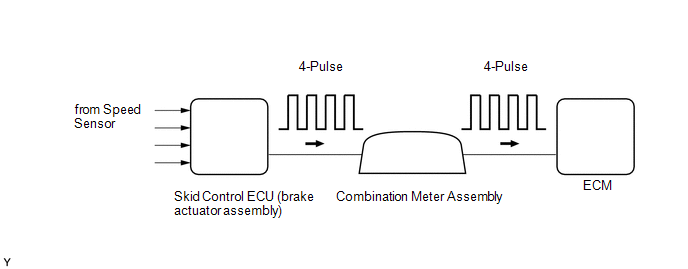
Vehicles which are equipped with ABS (Anti-lock Brake System) detect the vehicle speed using the skid control ECU (brake actuator assembly) and speed sensors. Each speed sensor monitors the wheel rotation speed and sends a signal to the skid control ECU (brake actuator assembly). The skid control ECU (brake actuator assembly) converts the wheel speed signals into a 4-pulse signal and transmits it to the ECM via the combination meter assembly. The ECM determines the vehicle speed based on the frequency of the pulse signal.
HINT:
- Various systems use the vehicle speed signal distributed from the combination meter assembly. Check all the components possibly related to the speed signal.
- A voltage of 12 V or 5 V is output from each ECU and then input to the combination meter assembly. The signal is changed to a pulse signal at the transistor in the combination meter assembly. Each ECU controls the respective system based on the pulse signal.
- If a short occurs in any of the ECUs or in the wire harness connected to an ECU, all systems using the speed signal will not operate normally.
| DTC No. | Detection Item | DTC Detection Condition | Trouble Area | MIL | Memory | Note |
|---|---|---|---|---|---|---|
| P050031 | Vehicle Speed Sensor "A" No Signal | While vehicle being driven, no vehicle speed sensor signal transmitted to ECM for 5.25 seconds (2 trip detection logic). |
| Comes on | DTC stored | SAE Code: P0500 |
MONITOR DESCRIPTION
If there is no speed signal from the combination meter assembly even though the ECM determines that the vehicle is being driven, the ECM interprets this as a malfunction in the speed signal circuit. The ECM then stores a DTC.
CONFIRMATION DRIVING PATTERN
CAUTION:
When performing the confirmation driving pattern, obey all speed limits and traffic laws.
HINT:
After repairs have been completed, clear the DTCs and then check that the vehicle has returned to normal by performing the following All Readiness check procedure.
- Connect the GTS to the DLC3.
- Turn the ignition switch to ON and turn the GTS on.
- Clear the DTCs (even if no DTCs are stored, perform the clear DTC procedure).
- Turn the ignition switch off and wait for 2 minutes or more.
- Turn the ignition switch to ON and turn the GTS on.
- Start the engine.
- While driving the vehicle with any gear selected and the clutch engaged, allow the vehicle to decelerate so that fuel cut is performed for 6 seconds or more.
- Stop the vehicle.
- Enter the following menus: Powertrain / Engine / Utility / All Readiness.
- Input the DTC: P050031.
-
Check the DTC judgment result.
GTS Display
Description
NORMAL
- DTC judgment completed
- System normal
ABNORMAL
- DTC judgment completed
- System abnormal
INCOMPLETE
- DTC judgment not completed
- Perform driving pattern after confirming DTC enabling conditions
N/A
- Unable to perform DTC judgment
- Number of DTCs which do not fulfill DTC preconditions has reached ECU memory limit
HINT:
- If the judgment result shows NORMAL, the system is normal.
- If the judgment result shows ABNORMAL, the system has a malfunction.
- If the judgment result shows INCOMPLETE or N/A, perform the Confirmation Driving Pattern and check the DTC judgment result again.
WIRING DIAGRAM
Refer to SFI system DTC P050031.
Click here

PROCEDURE
| 1. | CHECK DTC OUTPUT (SFI SYSTEM) |
(a) Check for SFI system DTCs.
Powertrain > Engine > Trouble Codes| Result | Proceed to |
|---|---|
| DTCs are not output | A |
| DTCs are output | B |
| A |
 | REPLACE ECM |
| B |
 | GO TO SFI SYSTEM |
 Crankshaft Position Sensor "A" Signal Stuck in Range (P03352A,P033531)
DESCRIPTION The crankshaft position sensor system consists of a crankshaft position sensor plate (crankshaft pulley) and Magneto Resistance Element (MRE) type sensor...
 Transmission Fluid Temperature Sensor "A" Circuit Short To Ground (P071011)
DESCRIPTION The manual transaxle oil temperature sensor (temperature sensor) installed inside the manual transaxle assembly detects the temperature of the fluid in the transaxle and outputs signals to the ECM according to the fluid temperature...
Other information:
Toyota Yaris XP210 (2020-2026) Reapir and Service Manual: Tongue Plate Stopper
ComponentsCOMPONENTS ILLUSTRATION *1 TONGUE PLATE STOPPER - - ● Non-reusable part - - ReplacementREPLACEMENT PROCEDURE 1. REMOVE TONGUE PLATE STOPPER (a) Slide the tongue plate above the installation position of the tongue plate stopper, and temporarily hold it with adhesive tape...
Toyota Yaris XP210 (2020-2026) Reapir and Service Manual: Components
COMPONENTS ILLUSTRATION *1 CLUTCH MASTER CYLINDER GASKET *2 CLUTCH MASTER CYLINDER ASSEMBLY *3 CLUTCH MASTER CYLINDER PUSH ROD CLEVIS WITH HOLE PIN *4 CLUTCH MASTER CYLINDER TO FLEXIBLE HOSE TUBE *5 NO. 1 CLUTCH RESERVOIR HOSE - - Tightening torque for "Major areas involving basic vehicle performance such as moving/turning/stopping": N*m (kgf*cm, ft...
Categories
- Manuals Home
- Toyota Yaris Owners Manual
- Toyota Yaris Service Manual
- Adjustment
- Headlights
- To Set Speed
- New on site
- Most important about car
Supplemental Restraint System (SRS) Precautions
The front and side supplemental restraint systems (SRS) include different types of air bags. Please verify the different types of air bags which are equipped on your vehicle by locating the “SRS AIRBAG” location indicators. These indicators are visible in the area where the air bags are installed.
The air bags are installed in the following locations:
The steering wheel hub (driver air bag) The front passenger dashboard (front passenger air bag) The outboard sides of the front seatbacks (side air bags) The front and rear window pillars, and the roof edge along both sides (curtain air bags)