Toyota Yaris: Smart Key System (for Entry Function) / Back Door Entry Lock Function does not Operate
DESCRIPTION
If the entry lock function does not operate for the back door only, but the entry unlock function operates, the request code is being transmitted properly from the back door. In this case, there may be a problem related to the lock switch (connection between the back door opener switch assembly and certification ECU (smart key ECU assembly)).
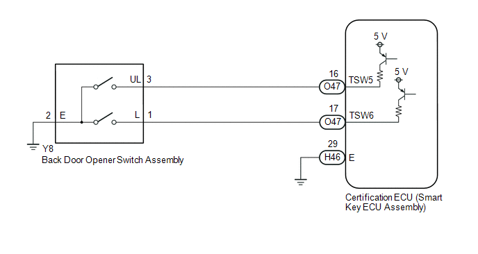
WIRING DIAGRAM
CAUTION / NOTICE / HINT
NOTICE:
- When using the GTS with the ignition switch off, connect the GTS to the DLC3 and turn a courtesy light switch on and off at intervals of 1.5 seconds or less until communication between the GTS and the vehicle begins. Then select the vehicle type under manual mode and enter the following menus: Body Electrical / Smart Key. While using the GTS, periodically turn a courtesy light switch on and off at intervals of 1.5 seconds or less to maintain communication between the GTS and the vehicle.
-
The smart key system (for Entry Function) uses the CAN communication system. Inspect the communication function by following How to Proceed with Troubleshooting. Troubleshoot the smart key system (for Entry Function) after confirming that the communication systems are functioning properly.
Click here

-
Before replacing the certification ECU (smart key ECU assembly), refer to Precaution.
Click here

- After repair, confirm that no DTCs are output.
- Check that there are no electrical key transmitter sub-assemblies in the vehicle.
PROCEDURE
| 1. | CHECK POWER DOOR LOCK CONTROL SYSTEM |
(a) When the door control switch on the multiplex network master switch assembly is operated, check that the back door lock and unlock according to the switch operation.
Click here

OK:
Back door lock/unlock operate normally.
| NG |
 | GO TO POWER DOOR LOCK CONTROL SYSTEM |
|

| 2. | INSPECT GTS (TRUNK LID/BACK DOOR LOCK SWITCH) |
(a) Read the Data List according to the display on the GTS.
Body Electrical > Smart Key > Data List| Tester Display | Measurement Item | Range | Normal Condition | Diagnostic Note |
|---|---|---|---|---|
| Trunk Lid/Back Door Lock Switch | Back door opener switch assembly (lock switch) | OFF or ON | OFF: Back door opener switch assembly (lock switch) not pressed ON: Back door opener switch assembly (lock switch) pressed |
|
| Tester Display |
|---|
| Trunk Lid/Back Door Lock Switch |
HINT:
When checking the operation of the entry lock function several times, it can be operated up to 2 times consecutively. To operate the function 3 times or more consecutively, the doors need to be unlocked once. However, this is only for the entry lock function, other door lock operations, such as a wireless door lock operation can be performed consecutively.
OK:
The GTS display changes correctly in response to the operation of the back door opener switch assembly.
| OK |
 | REPLACE CERTIFICATION ECU (SMART KEY ECU ASSEMBLY) |
|

| 3. | CHECK HARNESS AND CONNECTOR (BACK DOOR OPENER SWITCH ASSEMBLY - CERTIFICATION ECU (SMART KEY ECU ASSEMBLY)) |
(a) Disconnect the O47 certification ECU (smart key ECU assembly) connector.
(b) Disconnect the Y8 back door opener switch assembly connector.
(c) Measure the resistance according to the value(s) in the table below.
Standard Resistance:
| Tester Connection | Condition | Specified Condition |
|---|---|---|
| O47-17 (TSW6) - Y8-1 (L) | Always | Below 1 Ω |
| O47-17 (TSW6) or Y8-1 (L) - Other terminals and body ground | Always | 10 kΩ or higher |
| NG |
 | REPAIR OR REPLACE HARNESS OR CONNECTOR |
|

| 4. | INSPECT BACK DOOR OPENER SWITCH ASSEMBLY (LOCK SWITCH) |
Click here

| OK |
 | REPLACE CERTIFICATION ECU (SMART KEY ECU ASSEMBLY) |
| NG |
 | REPLACE BACK DOOR OPENER SWITCH ASSEMBLY |
 Back Door Entry Lock and Unlock Functions do not Operate
DESCRIPTION If the entry lock and unlock functions do not operate for the back door only, the request code may not be being transmitted from the back door...

Other information:
Toyota Yaris XP210 (2020-2026) Owner's Manual: Constant Monitoring
The following components of the air bag systems are monitored by a diagnostic system: Crash sensors, and diagnostic module (SAS unit) Front air bag sensors Air bag modules Side crash sensors Air bag/Front seat belt pretensioner system warning light Front seat belt pretensioners Related wiring Front passenger air bag deactivation indicator light Front passenger occupant classification sensor Front passenger occupant classification module The diagnostic module continuously monitors the system’s readiness...
Toyota Yaris XP210 (2020-2026) Reapir and Service Manual: Outer Rear View Mirror Glass
ComponentsCOMPONENTS ILLUSTRATION *1 OUTER MIRROR - - RemovalREMOVAL CAUTION / NOTICE / HINT HINT: Use the same procedure for the RH side and LH side. The following procedure is for the LH side. PROCEDURE 1. REMOVE OUTER MIRROR (a) Apply protective tape to the area as shown in the illustration...
Categories
- Manuals Home
- Toyota Yaris Owners Manual
- Toyota Yaris Service Manual
- Headlights
- To Set Speed
- How to use USB mode
- New on site
- Most important about car
Turning the Engine Off
Stop the vehicle completely. Manual transaxle: Shift into neutral and set the parking brake.Automatic transaxle: Shift the selector lever to the P position and set the parking brake.
Press the push button start to turn off the engine. The ignition position is off.