Toyota Yaris: Smart Key System (for Entry Function) / Back Door Entry Lock and Unlock Functions do not Operate
DESCRIPTION
If the entry lock and unlock functions do not operate for the back door only, the request code may not be being transmitted from the back door. If the entry functions for other doors operate properly, communication between the electrical key transmitter sub-assembly and the smart door control receiver assembly is normal. In this case, there may be a problem with request code transmission (communication between the certification ECU (smart key ECU assembly) and electrical key antenna (outside luggage compartment)) or there may be wave interference.
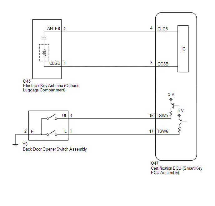
WIRING DIAGRAM
CAUTION / NOTICE / HINT
NOTICE:
- When using the GTS with the ignition switch off, connect the GTS to the DLC3 and turn a courtesy light switch on and off at intervals of 1.5 seconds or less until communication between the GTS and the vehicle begins. Then select the vehicle type under manual mode and enter the following menus: Body Electrical / Smart Key. While using the GTS, periodically turn a courtesy light switch on and off at intervals of 1.5 seconds or less to maintain communication between the GTS and the vehicle.
-
The smart key system (for Entry Function) uses the CAN communication system. Inspect the communication function by following How to Proceed with Troubleshooting. Troubleshoot the smart key system (for Entry Function) after confirming that the communication systems are functioning properly.
Click here

-
Before replacing the certification ECU (smart key ECU assembly), refer to Precaution.
Click here

- After repair, confirm that no DTCs are output.
- Check that there are no electrical key transmitter sub-assemblies in the vehicle.
HINT:
- If the back door entry lock and unlock function does not operate, the cause of the malfunction may be stored in the certification ECU (smart key ECU assembly).
- If the cause of the malfunction is stored in the certification ECU (smart key ECU assembly), the following table is helpful in checking whether the malfunction was caused by wave interference.
| Tester Display |
|---|
| Vehicle Control History (RoB) |
PROCEDURE
| 1. | CHECK POWER DOOR LOCK CONTROL SYSTEM |
(a) When the door control switch on the multiplex network master switch assembly is operated, check that the back door lock and unlock according to the switch operation.
Click here

OK:
Back door lock/unlock operate normally.
| NG |
 | GO TO POWER DOOR LOCK CONTROL SYSTEM |
|

| 2. | CHECK WAVE ENVIRONMENT |
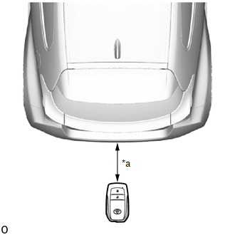
| (a) Bring the electrical key transmitter sub-assembly approximately 0.3 m (0.984 ft.) from the electrical key antenna (outside luggage compartment) and perform an entry back door open/lock function check. Click here
HINT:
|
|


| Result | Proceed to |
|---|---|
| Entry function does not operate normally | A |
| Entry function operates normally | B |
| B |
 | AFFECTED BY WAVE INTERFERENCE |
|

| 3. | READ VALUE USING GTS (TRUNK LID/BACK DOOR LOCK SWITCH, TRUNK LID/BACK DOOR UNLOCK SWITCH) |
(a) Read the Data List according to the display on the GTS.
Body Electrical > Smart Key > Data List| Tester Display | Measurement Item | Range | Normal Condition | Diagnostic Note |
|---|---|---|---|---|
| Trunk Lid/Back Door Lock Switch | Back door opener switch assembly (lock switch) | OFF or ON | OFF: Back door opener switch assembly (lock switch) not pressed ON: Back door opener switch assembly (lock switch) pressed |
|
| Trunk Lid/Back Door Unlock Switch | Back door opener switch assembly (open switch) | OFF or ON | OFF: Back door opener switch assembly (open switch) not pressed ON: Back door opener switch assembly (open switch) pressed |
|
| Tester Display |
|---|
| Trunk Lid/Back Door Lock Switch |
| Trunk Lid/Back Door Unlock Switch |
OK:
The GTS display changes correctly in response to the operation of the back door opener switch assembly.
| NG |
 | GO TO STEP 8 |
|

| 4. | CHECK KEY DIAGNOSTIC MODE |
(a) Check the following antenna in key diagnostic mode.
Body Electrical > Entry&Start > Utility| Tester Display |
|---|
| Communication Check(Key Diag Mode) |
| (b) Select either channel 1 or channel 2 and perform the key diagnostic mode inspection for each channel. (1) Check the electrical key antenna (outside luggage compartment): When the electrical key transmitter sub-assembly is brought within 0.7 to 1 m (2.30 to 3.28 ft.) of the electrical key antenna (outside luggage compartment), check that the wireless buzzer sounds. HINT:
|
|
| Result | Proceed to |
|---|---|
| Wireless buzzer does not sound | A |
| Wireless buzzer sounds | B |
| B |
 | REPLACE CERTIFICATION ECU (SMART KEY ECU ASSEMBLY) |
|

| 5. | CHECK HARNESS AND CONNECTOR (ELECTRICAL KEY ANTENNA (OUTSIDE LUGGAGE COMPARTMENT) - CERTIFICATION ECU (SMART KEY ECU ASSEMBLY)) |
(a) Disconnect the O47 certification ECU (smart key ECU assembly) connector.
(b) Disconnect the O45 electrical key antenna (outside luggage compartment) connector.
(c) Measure the resistance according to the value(s) in the table below.
Standard Resistance:
| Tester Connection | Condition | Specified Condition |
|---|---|---|
| O47-4 (CLG8) - O45-2 (ANTE8) | Always | Below 1 Ω |
| O47-3 (CG8B) - O45-1 (CLGB) | Always | Below 1 Ω |
| O47-4 (CLG8) or O45-2 (ANTE8) - Other terminals and body ground | Always | 10 kΩ or higher |
| O47-3 (CG8B) or O45-1 (CLGB) - Other terminals and body ground | Always | 10 kΩ or higher |
(d) Reconnect the O47 certification ECU (smart key ECU assembly) connector.
| NG |
 | REPAIR OR REPLACE HARNESS OR CONNECTOR |
|

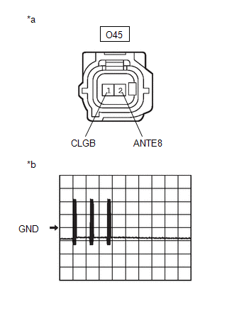
| 6. | INSPECT CERTIFICATION ECU (SMART KEY ECU ASSEMBLY) (OUTPUT TO ELECTRICAL KEY ANTENNA (OUTSIDE LUGGAGE COMPARTMENT)) |
| (a) Using an oscilloscope, check the waveform. OK:
|
|
| OK |
 | REPLACE ELECTRICAL KEY ANTENNA (OUTSIDE LUGGAGE COMPARTMENT) |
|

| 7. | CHECK ENTRY OPERATION |
(a) Connect all connectors and check that the function operates normally.
Click here

| Result | Proceed to |
|---|---|
| Entry function operates normally | A |
| Entry function does not operate normally | B |
| A |
 | END (CONNECTOR WAS NOT CONNECTED SECURELY) |
| B |
 | REPLACE CERTIFICATION ECU (SMART KEY ECU ASSEMBLY) |
| 8. | CHECK HARNESS AND CONNECTOR (BACK DOOR OPENER SWITCH ASSEMBLY - CERTIFICATION ECU (SMART KEY ECU ASSEMBLY) AND BODY GROUND) |
(a) Disconnect the O47 certification ECU (smart key ECU assembly) connector.
(b) Disconnect the Y8 back door opener switch assembly connector.
(c) Measure the resistance according to the value(s) in the table below.
Standard Resistance:
| Tester Connection | Condition | Specified Condition |
|---|---|---|
| O47-16 (TSW5) - Y8-3 (UL) | Always | Below 1 Ω |
| O47-17 (TSW6) - Y8-1 (L) | Always | Below 1 Ω |
| Y8-2 (E) - Other terminals and body ground | Always | Below 1 Ω |
| O47-16 (TSW5) or Y8-3 (UL) - Other terminals and body ground | Always | 10 kΩ or higher |
| O47-17 (TSW6) or Y8-1 (L) - Other terminals and body ground | Always | 10 kΩ or higher |
| NG |
 | REPAIR OR REPLACE HARNESS OR CONNECTOR |
|

| 9. | INSPECT BACK DOOR OPENER SWITCH ASSEMBLY |
Click here

| NG |
 | REPLACE BACK DOOR OPENER SWITCH ASSEMBLY |
|

| 10. | CHECK ENTRY OPERATION |
(a) Connect all connectors and check that the function operates normally.
Click here

| Result | Proceed to |
|---|---|
| Entry function operates normally | A |
| Entry function does not operate normally | B |
| A |
 | END (CONNECTOR WAS NOT CONNECTED SECURELY) |
| B |
 | REPLACE CERTIFICATION ECU (SMART KEY ECU ASSEMBLY) |
 Back Door Entry Unlock Function does not Operate
DESCRIPTION If the entry unlock function does not operate for the back door only, but the entry lock function operates, the request code is being transmitted properly from the back door...
 Back Door Entry Lock Function does not Operate
DESCRIPTION If the entry lock function does not operate for the back door only, but the entry unlock function operates, the request code is being transmitted properly from the back door...
Other information:
Toyota Yaris XP210 (2020-2026) Reapir and Service Manual: Evaporator Temperature Sensor Circuit Short to Battery or Open (P053515)
DESCRIPTION The No. 1 cooler thermistor is installed to the evaporator in the air conditioner unit to detect the temperature of the cooled air that has passed through the evaporator, which is used to control the air conditioning system. It sends signals to the air conditioning amplifier assembly...
Toyota Yaris XP210 (2020-2026) Reapir and Service Manual: Adjustment
ADJUSTMENT PROCEDURE 1. SECURE VEHICLE (a) Fully apply the parking brake and chock a wheel. CAUTION: Make sure to apply the parking brake and chock a wheel before performing this procedure. If the vehicle is not secure and the shift lever is moved to neutral, the vehicle may suddenly move, possibly resulting in an accident or serious injury...
Categories
- Manuals Home
- Toyota Yaris Owners Manual
- Toyota Yaris Service Manual
- Diagnostic Trouble Code Chart
- Immobilizer System
- Battery Monitor Module General Electrical Failure (P058A01)
- New on site
- Most important about car
Supplemental Restraint System (SRS) Precautions
The front and side supplemental restraint systems (SRS) include different types of air bags. Please verify the different types of air bags which are equipped on your vehicle by locating the “SRS AIRBAG” location indicators. These indicators are visible in the area where the air bags are installed.
The air bags are installed in the following locations:
The steering wheel hub (driver air bag) The front passenger dashboard (front passenger air bag) The outboard sides of the front seatbacks (side air bags) The front and rear window pillars, and the roof edge along both sides (curtain air bags)