Toyota Yaris: Shift Lever Assembly / Installation
INSTALLATION
PROCEDURE
1. INSTALL FLOOR SHIFT SHIFT LEVER ASSEMBLY
(a) Install the floor shift shift lever assembly to the vehicle body with the 4 bolts.
Torque:
12 N·m {122 kgf·cm, 9 ft·lbf}
(b) Engage the 4 clamps to connect the wire harness to the floor shift shift lever assembly.
2. CONNECT TRANSMISSION CONTROL CABLE ASSEMBLY
| (a) Rotate the nut counterclockwise approximately 180° and, while holding the nut in that position, press in the stopper. |
|
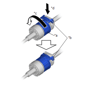
| (b) Install the transmission control shift cable to the floor shift shift lever assembly, check that the position of the stopper is the same as shown in the illustration. NOTICE: Do not forcibly pull the transmission control cable assembly into the cabin. |
|
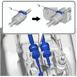
(c) Install the transmission control select cable to the floor shift shift lever assembly, check that the position of the stopper is the same as shown in the illustration.
NOTICE:
Do not forcibly pull the transmission control cable assembly into the cabin.
| (d) Connect the transmission control shift cable to the floor shift shift lever assembly. |
|
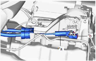
(e) Connect the transmission control select cable to the floor shift shift lever assembly with the clip.
3. ADJUST TRANSMISSION CONTROL CABLE ASSEMBLY
Click here

4. INSTALL REAR CONSOLE BOX ASSEMBLY
Click here

 Removal
REMOVAL PROCEDURE 1. SECURE VEHICLE (a) Fully apply the parking brake and chock a wheel. CAUTION:
Make sure to apply the parking brake and chock a wheel before performing this procedure...
 Speed Sensor
ComponentsCOMPONENTS ILLUSTRATION
*1 TRANSMISSION REVOLUTION SENSOR *2 O-RING *3 NO. 1 ENGINE UNDER COVER ASSEMBLY - -
N*m (kgf*cm, ft...
Other information:
Toyota Yaris XP210 (2020-2026) Reapir and Service Manual: Steering Pad Switch Circuit
DESCRIPTION The combination meter assembly and steering pad switch assembly are connected via direct line. The multi-information display in the combination meter assembly are operated using the switches of the steering pad switch assembly. WIRING DIAGRAM CAUTION / NOTICE / HINT NOTICE: When replacing the combination meter assembly, always replace it with a new one...
Toyota Yaris XP210 (2020-2026) Owner's Manual: Brake Assist
During emergency braking situations when it is necessary to depress the brake pedal with greater force, the brake assist system provides braking assistance, thus enhancing braking performance. When the brake pedal is depressed hard or depressed more quickly, the brakes apply more firmly...
Categories
- Manuals Home
- Toyota Yaris Owners Manual
- Toyota Yaris Service Manual
- Immobilizer System
- Fuel Gauge
- Auto Lock/Unlock Function
- New on site
- Most important about car
Keys

To use the auxiliary key, press the knob and pull out the auxiliary key from the smart key.
