Toyota Yaris: Shift Lever Assembly / Removal
REMOVAL
PROCEDURE
1. SECURE VEHICLE
(a) Fully apply the parking brake and chock a wheel.
CAUTION:
-
Make sure to apply the parking brake and chock a wheel before performing this procedure.
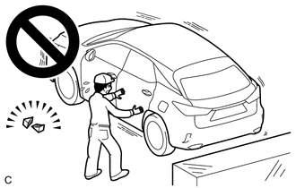
- If the vehicle is not secure and the shift lever is moved to neutral, the vehicle may suddenly move, possibly resulting in an accident or serious injury.
2. REMOVE REAR CONSOLE BOX ASSEMBLY
Click here

3. DISCONNECT TRANSMISSION CONTROL CABLE ASSEMBLY
| (a) Remove the clip and disconnect the transmission control select cable from the floor shift shift lever assembly. |
|
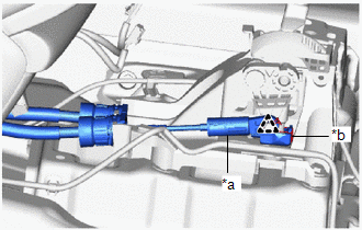
(b) Disconnect the transmission control shift cable from the floor shift shift lever assembly.
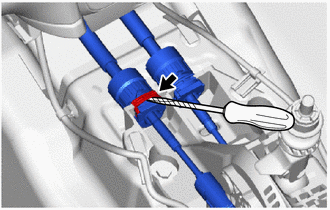
| (c) Using a screwdriver, pull out the stopper of the transmission control select cable. NOTICE: Do not remove the stopper. If it is removed, reinstall it to its original position. |
|
| (d) Rotate the nut clockwise approximately 180° and, while holding the nut in that position, disconnect the transmission control select cable from the floor shift shift lever assembly. NOTICE:
|
|
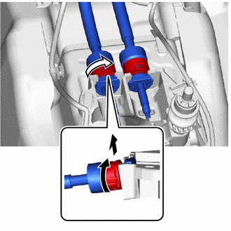
(e) Disconnect the transmission control shift cable from the floor shift shift lever assembly in the same manner as the transmission control select cable.
4. REMOVE FLOOR SHIFT SHIFT LEVER ASSEMBLY
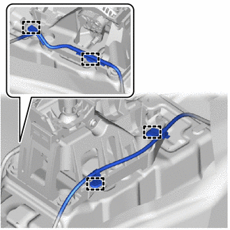
| (a) Disengage the 4 clamps to disconnect the wire harness from the floor shift shift lever assembly. |
|
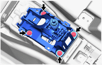
| (b) Remove the 4 bolts and floor shift shift lever assembly from the vehicle body. |
|
 Components
C..
 Installation
INSTALLATION PROCEDURE 1. INSTALL FLOOR SHIFT SHIFT LEVER ASSEMBLY (a) Install the floor shift shift lever assembly to the vehicle body with the 4 bolts...
Other information:
Toyota Yaris XP210 (2020-2026) Reapir and Service Manual: Components
C..
Toyota Yaris XP210 (2020-2026) Reapir and Service Manual: Air Conditioning Amplifier Communication Stop Mode
DESCRIPTION Detection Item Symptom Trouble Area Air Conditioning Amplifier Communication Stop Mode Communication stop for "Air Conditioning Amplifier" is indicated on the "Communication Bus Check" screen of the GTS. Click here Air conditioning amplifier assembly branch line or connector Power source circuit of air conditioning amplifier assembly Air conditioning amplifier assembly ground circuit Air conditioning amplifier assembly WIRING DIAGRAM CAUTION / NOTICE / HINT CAUTION: When performing the confirmation driving pattern, obey all speed limits and traffic laws...
Categories
- Manuals Home
- Toyota Yaris Owners Manual
- Toyota Yaris Service Manual
- Diagnostic Trouble Code Chart
- Opening and Closing the Liftgate/Trunk Lid
- Adjustment
- New on site
- Most important about car
Front Seat Belt Pretensioners
The front seat belt pretensioners are designed to deploy in moderate or severe frontal, near frontal collisions.
In addition, the pretensioners operate when a side collision or a rollover accident is detected. The pretensioners operate differently depending on what types of air bags are equipped. For more details about the seat belt pretensioner operation, refer to the SRS Air Bag Deployment Criteria.