Toyota Yaris: Window / Glass / Power Window Master Switch
Components
COMPONENTS
ILLUSTRATION
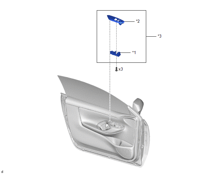
| *1 | MULTIPLEX NETWORK MASTER SWITCH ASSEMBLY | *2 | FRONT ARMREST BASE UPPER PANEL |
| *3 | MULTIPLEX NETWORK MASTER SWITCH ASSEMBLY WITH FRONT ARMREST BASE UPPER PANEL | - | - |
Removal
REMOVAL
PROCEDURE
1. REMOVE MULTIPLEX NETWORK MASTER SWITCH ASSEMBLY WITH FRONT ARMREST BASE UPPER PANEL
Click here
.gif)
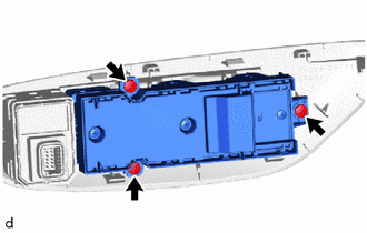
2. REMOVE MULTIPLEX NETWORK MASTER SWITCH ASSEMBLY
| (a) Remove the 3 screws and multiplex network master switch assembly. |
|
Inspection
INSPECTION
PROCEDURE
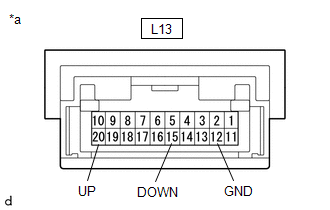
1. INSPECT MULTIPLEX NETWORK MASTER SWITCH ASSEMBLY
(a) Check the resistance.
| (1) Measure the resistance according to the value(s) in the table below. Standard Resistance:
If the result is not as specified, replace the multiplex network master switch assembly. |
|
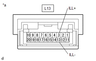
(b) Check that the LED illuminates.
| (1) Apply auxiliary battery voltage to the multiplex network master switch assembly and check that the LED illuminate. OK:
If the result is not as specified, replace the multiplex network master switch assembly. |
|
Installation
INSTALLATION
PROCEDURE
1. INSTALL MULTIPLEX NETWORK MASTER SWITCH ASSEMBLY
(a) Install the multiplex network master switch assembly with the 3 screws.
2. INSTALL MULTIPLEX NETWORK MASTER SWITCH ASSEMBLY WITH FRONT ARMREST BASE UPPER PANEL
Click here
.gif)
 Jam Protection Function does not Operate
DESCRIPTION This symptom may occur for any of the power windows. The jam protection function operates within a specified range during the manual up or auto up operation...

Other information:
Toyota Yaris XP210 (2020-2026) Reapir and Service Manual: Steering Angle Sensor Supply Voltage Circuit Circuit Short to Ground or Open (C14FE14)
DESCRIPTION This DTC is stored when the skid control ECU (brake actuator assembly) receives a power supply malfunction signal from the steering sensor. DTC No. Detection Item DTC Detection Condition Trouble Area DTC Output from C14FE14 Steering Angle Sensor Supply Voltage Circuit Circuit Short to Ground or Open When the +BS terminal voltage is from 9...
Toyota Yaris XP210 (2020-2026) Reapir and Service Manual: On-vehicle Inspection
ON-VEHICLE INSPECTION PROCEDURE 1. INSPECT MASS AIR FLOW METER HINT: Perform "Inspection After Repair" after replacing the mass air flow meter. Click here (a) Read the value of Data List item "Mass Air Flow Sensor" using the GTS. NOTICE: Perform the inspection of the mass air flow meter while it is installed to the air cleaner cap sub-assembly (installed to the vehicle)...
Categories
- Manuals Home
- Toyota Yaris Owners Manual
- Toyota Yaris Service Manual
- G16e-gts (engine Mechanical)
- How to use USB mode
- Auto Lock/Unlock Function
- New on site
- Most important about car
Fuel Gauge
The fuel gauge shows approximately how much fuel is remaining in the tank when the ignition is switched ON. We recommend keeping the tank over 1/4 full.
