Toyota Yaris: Cylinder Head / Inspection
INSPECTION
PROCEDURE
1. INSPECT CYLINDER HEAD SUB-ASSEMBLY
(a) Using a precision straightedge and feeler gauge, measure the warpage of the contact surfaces where the cylinder head sub-assembly contacts the cylinder block sub-assembly, intake manifold and exhaust manifold.
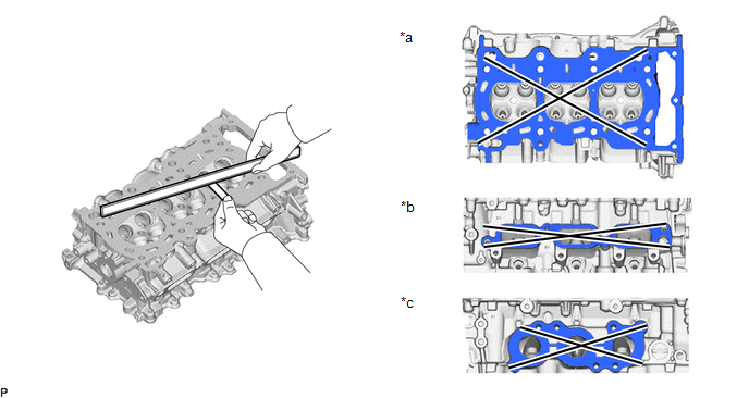
| *a | Bottom Side | *b | Intake Manifold Side |
| *c | Exhaust Manifold Side | - | - |
Maximum Warpage:
| Item | Specified Condition |
|---|---|
| Bottom side | 0.05 mm (0.00197 in.) |
| Intake manifold side | 0.10 mm (0.00394 in.) |
| Exhaust manifold side | 0.10 mm (0.00394 in.) |
HINT:
If the warpage is more than the maximum, replace the cylinder head sub-assembly.
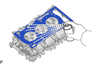
| (b) Using a dye penetrant, check the intake ports, exhaust ports and cylinder head sub-assembly surface for cracks. HINT: If cracks are found, replace the cylinder head sub-assembly. |
|
2. INSPECT COMPRESSION SPRING
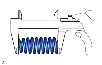
(a) Intake Side:
| (1) Using a vernier caliper, measure the free length of the compression spring. Standard Free Length: 57.70 mm (2.27 in.) NOTICE: Compression springs come in 2 different lengths. Make sure all compression springs are the same length when replacing them. |
|
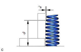
| (2) Using a steel square, measure the deviation of the compression spring. Maximum Deviation (Reference): 1.0 mm (0.0394 in.) HINT: If the deviation is more than the maximum, replace the compression spring. |
|

(b) Exhaust Side:
| (1) Using a vernier caliper, measure the free length of the compression spring. Standard Free Length: 59.11 mm (2.33 in.) NOTICE: Compression springs come in 2 different lengths. Make sure all compression springs are the same length when replacing them. |
|

| (2) Using a steel square, measure the deviation of the compression spring. Maximum Deviation (Reference): 1.0 mm (0.0394 in.) HINT: If the deviation is more than the maximum, replace the compression spring. |
|
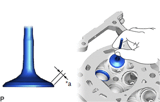
3. INSPECT INTAKE VALVE
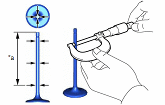
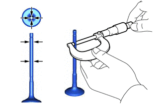
| (a) Using a micrometer, measure the diameter of the valve stem. Standard Valve Stem Diameter: 5.470 to 5.485 mm (0.215 to 0.216 in.) HINT: If the valve stem diameter is not as specified, check the intake valve guide bush oil clearance. |
|
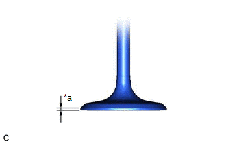
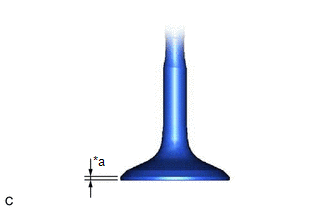
| (b) Using a vernier caliper, measure the valve head margin thickness. Standard Margin Thickness: 1.23 to 1.25 mm (0.0484 to 0.0492 in.) Minimum Margin Thickness: 0.5 mm (0.0197 in.) HINT: If the margin thickness is less than the minimum, replace the intake valve. |
|
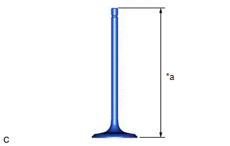
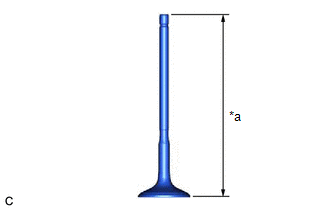
| (c) Using a vernier caliper, measure the overall length of the intake valve. Standard Overall Length: 102.45 mm (4.03 in.) Minimum Overall Length: 101.95 mm (4.01 in.) HINT: If the overall length is less than the minimum, replace the intake valve. |
|
4. INSPECT EXHAUST VALVE
| (a) Using a micrometer, measure the diameter of the valve stem. Standard Valve Stem Diameter: 5.470 to 5.485 mm (0.215 to 0.216 in.) HINT: If the valve stem diameter is not as specified, check the exhaust valve guide bush oil clearance. |
|
| (b) Using a vernier caliper, measure the valve head margin thickness. Standard Margin Thickness: 1.0 mm (0.0394 in.) Minimum Margin Thickness: 0.5 mm (0.0197 in.) HINT: If the margin thickness is less than the minimum, replace the exhaust valve. |
|
| (c) Using a vernier caliper, measure the overall length of the exhaust valve. Standard Overall Length: 117.05 mm (4.608 in.) Minimum Overall Length: 116.55 mm (4.59 in.) HINT: If the overall length is less than the minimum, replace the exhaust valve. |
|
5. INSPECT VALVE GUIDE BUSH OIL CLEARANCE
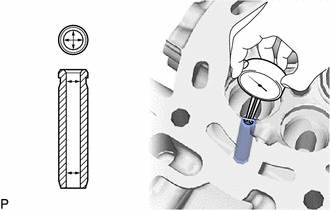
| (a) Using a caliper gauge, measure the inside diameter of the valve guide bush. Standard Valve Guide Bush Inside Diameter: 5.51 to 5.53 mm (0.217 to 0.218 in.) |
|
(b) Subtract the valve stem diameter measurement from the valve guide bush inside diameter measurement.
Standard Oil Clearance:
| Item | Specified Condition |
|---|---|
| Intake Side | 0.025 to 0.060 mm (0.000984 to 0.00236 in.) |
| Exhaust Side | 0.030 to 0.065 mm (0.00118 to 0.00256 in.) |
Maximum Oil Clearance:
| Item | Specified Condition |
|---|---|
| Intake Side | 0.080 mm (0.00315 in.) |
| Exhaust Side | 0.10 mm (0.00394 in.) |
HINT:
- Oil clearance = Valve guide bush inside - Valve stem diameter
- If the oil clearance is more than the maximum, replace the valve and valve guide bush.
6. INSPECT INTAKE VALVE SEAT
(a) Apply a light coat of Prussian blue to the valve face.
| (b) Lightly press the valve face against the intake valve seat. NOTICE: Do not rotate the valve while pressing it. |
|
(c) Check the valve face and intake valve seat by using the following procedure:
(1) If Prussian blue appears 360° around the entire intake valve face, the valve face is concentric.
HINT:
If the valve face is not concentric, replace the intake valve.
(2) If Prussian blue appears 360° around the entire intake valve seat, the intake valve seat and valve face are concentric.
HINT:
If the valve face is not concentric, resurface the intake valve seat.
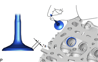
(3) Measure the width of the contact area of the intake valve seat and valve face.
Standard Width:
1.0 to 1.4 mm (0.0394 to 0.0551 in.)
7. INSPECT EXHAUST VALVE SEAT
(a) Apply a light coat of Prussian blue to the valve face.
| (b) Lightly press the valve face against the exhaust valve seat. NOTICE: Do not rotate the valve while pressing it. |
|
(c) Check the valve face and exhaust valve seat by using the following procedure:
(1) If Prussian blue appears 360° around the entire exhaust valve face, the valve face is concentric.
HINT:
If the valve face is not concentric, replace the exhaust valve.
(2) If Prussian blue appears 360° around the entire exhaust valve seat, the exhaust valve seat and valve face are concentric.
HINT:
If the valve face is not concentric, resurface the exhaust valve seat.
(3) Measure the width of the contact area of the exhaust valve seat and valve face.
Standard Width:
1.3 to 1.7 mm (0.0512 to 0.0669 in.)
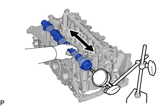
8. INSPECT CAMSHAFT THRUST CLEARANCE
(a) Clean the No. 1 camshaft bearing cap, No. 2 camshaft bearing cap, 2 No. 3 camshaft bearing caps, No. 4 camshaft bearing cap, camshaft journals.
(b) Place the intake camshaft sub-assembly and exhaust camshaft sub-assembly on the cylinder head sub-assembly.
(c) Install the camshaft bearing caps.
Click here

| (d) Using a dial indicator, measure the thrust clearance while moving the intake camshaft sub-assembly and exhaust camshaft sub-assembly back and forth. Standard Thrust Clearance:
Maximum Thrust Clearance:
HINT: If the thrust clearance is more than the maximum, replace the cylinder head sub-assembly. If the thrust surface is damaged, replace the camshaft. |
|
 Disassembly
DISASSEMBLY CAUTION / NOTICE / HINT The necessary procedures (adjustment, calibration, initialization, or registration) that must be performed after parts are removed and installed, or replaced during cylinder head removal/installation are shown below...
 Replacement
REPLACEMENT PROCEDURE 1. REPLACE INTAKE VALVE GUIDE BUSH (a) Heat the cylinder head sub-assembly to between 80 and 100°C (176 to 212°F). (b) Place the cylinder head sub-assembly on wooden blocks...
Other information:
Toyota Yaris XP210 (2020-2026) Reapir and Service Manual: Precaution
PRECAUTION PRECAUTION FOR REPLACING COMBINATION METER ASSEMBLY When replacing the combination meter assembly, always replace it with a new one. If a combination meter assembly which was installed to another vehicle is used, the information stored in it will not match the information from the vehicle and a DTC may be stored...
Toyota Yaris XP210 (2020-2026) Owner's Manual: Tiedown Hook-Rear
The hook positioned under the rear bumper on the right side is for tying down the vehicle during transport, and it cannot be used for towing other vehicles. It can be used as a towing hook only when the vehicle must be towed by another vehicle in an emergency case such as when the vehicle is stuck in snow, however, it may damage the bumper...
Categories
- Manuals Home
- Toyota Yaris Owners Manual
- Toyota Yaris Service Manual
- G16e-gts (engine Mechanical)
- How to use USB mode
- Maintenance
- New on site
- Most important about car
Fuel Gauge
The fuel gauge shows approximately how much fuel is remaining in the tank when the ignition is switched ON. We recommend keeping the tank over 1/4 full.
