Toyota Yaris: Cylinder Head / Replacement
REPLACEMENT
PROCEDURE
1. REPLACE INTAKE VALVE GUIDE BUSH
(a) Heat the cylinder head sub-assembly to between 80 and 100°C (176 to 212°F).
(b) Place the cylinder head sub-assembly on wooden blocks.
CAUTION:
Be sure to wear protective gloves.
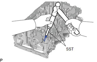
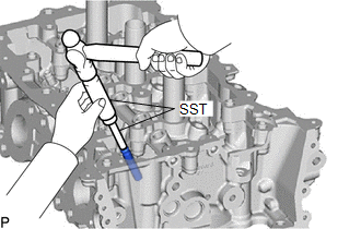
| (c) Using SST and a hammer, tap out the intake valve guide bush. SST: 09201-01055 SST: 09950-70010 09951-07100 |
|
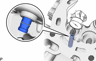
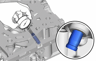
| (d) Using a caliper gauge, measure the intake valve guide bush bore diameter of the cylinder head sub-assembly. Standard Intake Valve Guide Bush Bore Diameter: 10.285 to 10.306 mm (0.405 to 0.406 in.) New Guide Bush Selection Chart:
Standard Bush Length: 41.3 to 41.7 mm (1.63 to 1.64 in.) HINT:
|
|
(e) Heat the cylinder head sub-assembly to between 80 and 100°C (176 to 212°F).
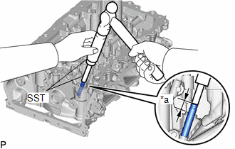
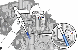
| (f) Using SST and a hammer, tap in the selected intake valve guide bush. SST: 09201-10000 09201-01050 SST: 09950-70010 09951-07100 Standard Protrusion Height: 13.35 to 13.60 mm (0.526 to 0.535 in.) |
|
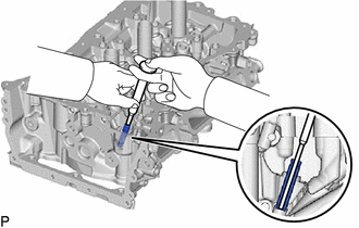
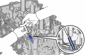
| (g) Using a sharp 5.5 mm reamer, ream the intake valve guide bush to obtain the standard oil clearance. Standard Oil Clearance: 0.025 to 0.060 mm (0.000984 to 0.00236 in.) |
|
2. REPLACE EXHAUST VALVE GUIDE BUSH
(a) Heat the cylinder head sub-assembly to between 80 and 100°C (176 to 212°F).
(b) Place the cylinder head sub-assembly on wooden blocks.
CAUTION:
Be sure to wear protective gloves.
| (c) Using SST and a hammer, tap out the exhaust valve guide bush. SST: 09201-01055 SST: 09950-70010 09951-07100 |
|
| (d) Using a caliper gauge, measure the exhaust valve guide bush bore diameter of the cylinder head sub-assembly. Standard Exhaust Valve Guide Bush Bore Diameter: 10.285 to 10.306 mm (0.405 to 0.406 in.) New Guide Bush Selection Chart:
Standard Bush Length: 43.3 to 43.7 mm (1.70 to 1.72 in.) HINT:
|
|
(e) Heat the cylinder head sub-assembly to between 80 and 100°C (176 to 212°F).
| (f) Using SST and a hammer, tap in the selected exhaust valve guide bush. SST: 09201-10000 09201-01050 SST: 09950-70010 09951-07100 Standard Protrusion Height: 13.75 to 14.00 mm (0.541 to 0.551 in.) |
|
| (g) Using a sharp 5.5 mm reamer, ream the exhaust valve guide bush to obtain the standard oil clearance. Standard Oil Clearance: 0.030 to 0.065 mm (0.00118 to 0.00256 in.) |
|
3. REPLACE RING PIN
NOTICE:
It is not necessary to remove the ring pins unless they are being replaced.
(a) Remove the 8 ring pins.
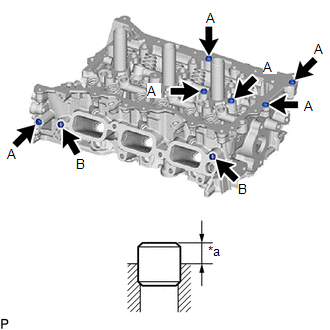
| (b) Using a plastic hammer, tap in 8 new ring pins to the cylinder head sub-assembly. Standard Protrusion Height: RING PIN (A) 3.0 to 5.0 mm (0.118 to 0.197 in.) RING PIN (B) 4.0 to 6.0 mm (0.157 to 0.236 in.) |
|
 Inspection
INSPECTION PROCEDURE 1. INSPECT CYLINDER HEAD SUB-ASSEMBLY (a) Using a precision straightedge and feeler gauge, measure the warpage of the contact surfaces where the cylinder head sub-assembly contacts the cylinder block sub-assembly, intake manifold and exhaust manifold...
 Reassembly
REASSEMBLY PROCEDURE 1. INSTALL SPARK PLUG TUBE HINT: When using a new cylinder head sub-assembly, the spark plug tubes must be replaced. (a) Apply adhesive to a new spark plug tube as shown in the illustration...
Other information:
Toyota Yaris XP210 (2020-2026) Reapir and Service Manual: 4wd Control Switch
ComponentsCOMPONENTS ILLUSTRATION *1 CONSOLE BOX ASSEMBLY *2 4WD CONTROL SWITCH (NO. 2 COMBINATION SWITCH ASSEMBLY) RemovalREMOVAL PROCEDURE 1. REMOVE CONSOLE BOX ASSEMBLY Click here 2. REMOVE 4WD CONTROL SWITCH (NO. 2 COMBINATION SWITCH ASSEMBLY) (a) Remove the 3 screws and 4WD control switch (No...
Toyota Yaris XP210 (2020-2026) Reapir and Service Manual: Speed Signal Circuit
DESCRIPTION HINT: This circuit is used for the systems connected to terminal +S. This signal is not used for combination meter assembly operation. Combination meter assembly components such as the speedometer operate using data received via CAN communication...
Categories
- Manuals Home
- Toyota Yaris Owners Manual
- Toyota Yaris Service Manual
- Fuel Gauge
- Power Integration No.1 System Missing Message (B235287,B235587,B235787-B235987)
- To Set Speed
- New on site
- Most important about car
Break-In Period
No special break-in is necessary, but a few precautions in the first 600 miles (1,000 km) may add to the performance, economy, and life of the vehicle.
Do not race the engine. Do not maintain one constant speed, either slow or fast, for a long period of time. Do not drive constantly at full-throttle or high engine rpm for extended periods of time. Avoid unnecessary hard stops. Avoid full-throttle starts.