Toyota Yaris: Roof Headlining / Removal
REMOVAL
CAUTION / NOTICE / HINT
HINT:
When the cable is disconnected / reconnected to the auxiliary battery terminal, systems temporarily stop operating. However, each system has a function that completes learning the first time the system is used.
-
Learning completes when vehicle is driven
Effect/Inoperative Function When Necessary Procedures are not Performed
Necessary Procedures
Link
Lane tracing assist system
Drive the vehicle straight ahead at 35 km/h (22 mph) or more for 5 second or more.

Pre-collision system
Stop and start system
Drive the vehicle until stop and start control is permitted (approximately 5 to 60 minutes)

-
Learning completes when vehicle is operated normally
Effect/Inoperative Function When Necessary Procedures are not Performed
Necessary Procedures
Link
Power door lock control system
- Back door opener
Perform door unlock operation with door control switch or electrical key transmitter sub-assembly switch.

Air conditioning system
After the ignition switch is turned to ON, the servo motor standard position is recognized.
-
PROCEDURE
1. REMOVE INSTRUMENT PANEL SUB-ASSEMBLY
Click here

2. REMOVE NO. 2 HEATER TO REGISTER DUCT SUB-ASSEMBLY
Click here

3. REMOVE FRONT SEAT ASSEMBLY LH
Click here

4. REMOVE FRONT SEAT ASSEMBLY RH
HINT:
Use the same procedure as for the LH side.
5. REMOVE PACKAGE TRAY TRIM PANEL ASSEMBLY
| (a) Disengage the hooks to remove the package tray trim panel assembly. |
|
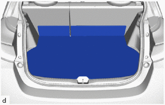
6. REMOVE DECK BOARD ASSEMBLY
| (a) Remove the deck board assembly. |
|
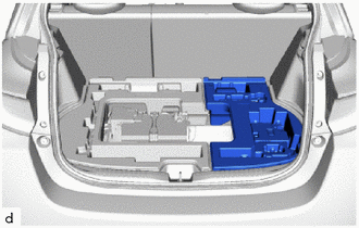
7. REMOVE DECK FLOOR BOX RH
| (a) Remove the deck floor box RH. |
|
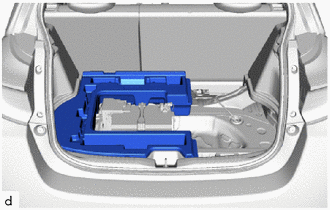
8. REMOVE DECK FLOOR BOX LH
| (a) Remove the deck floor box LH. |
|
9. REMOVE FRONT DOOR OPENING TRIM WEATHERSTRIP LH
Click here

10. REMOVE FRONT DOOR OPENING TRIM WEATHERSTRIP RH
HINT:
Use the same procedure as for the LH side.
11. REMOVE REAR SEAT ASSEMBLY
Click here

12. REMOVE LAP BELT OUTER ANCHOR COVER
HINT:
Use the same procedure as for the opposite side.
Click here

13. DISCONNECT FRONT SEAT OUTER BELT ASSEMBLY LH
Click here

14. DISCONNECT FRONT SEAT OUTER BELT ASSEMBLY RH
HINT:
Use the same procedure as for the LH side.
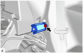
15. REMOVE REAR SEATBACK HINGE SUB-ASSEMBLY LH
| (a) Loosen the bolt to remove the rear seatback hinge sub-assembly LH. |
|
16. REMOVE REAR SEATBACK HINGE SUB-ASSEMBLY RH
HINT:
Use the same procedure as for the RH side.
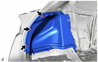
17. REMOVE QUARTER TRIM PANEL ASSEMBLY LH
(a) Disengage the claws, clips and guide to remove the quarter trim panel assembly LH as shown in the illustration.
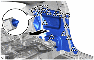
 | Remove in this Direction |
18. REMOVE QUARTER TRIM PANEL ASSEMBLY RH
HINT:
Use the same procedure as for the LH side.
19. REMOVE CENTER PILLAR UPPER GARNISH LH
(a) Remove the 2 clips.
 | Place Hands Here |
 | Remove in this Direction (1) |
 | Remove in this Direction (2) |
(b) Disengage the clip and guides to remove the center pillar upper garnish LH as shown in the illustration.
20. REMOVE CENTER PILLAR UPPER GARNISH RH
HINT:
Use the same procedure as for the LH side.
21. REMOVE NO. 1 ROOF HEADLINING MOULDING LH
| (a) Remove the No. 1 roof headlining moulding LH. |
|
22. REMOVE NO. 1 ROOF HEADLINING MOULDING RH
HINT:
Use the same procedure as for the LH side.
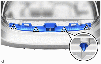
23. REMOVE DECK TRIM REAR COVER
| (a) Disengage the clips to remove the deck trim rear cover. |
|
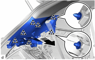
24. REMOVE DECK TRIM SIDE PANEL ASSEMBLY LH
| (a) Remove the 3 clips and deck trim side panel assembly LH. |
|
25. REMOVE DECK TRIM SIDE PANEL ASSEMBLY RH
HINT:
Use the same procedure as for the LH side.
26. DISCONNECT REAR SEAT OUTER BELT ASSEMBLY LH
Click here

27. DISCONNECT REAR SEAT OUTER BELT ASSEMBLY RH
HINT:
Use the same procedure as for the LH side.
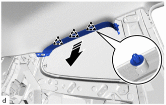
28. REMOVE INNER ROOF SIDE GARNISH LH
(a) Disengage the clips to remove the inner roof side garnish LH as shown in the illustration.
 | Remove in this Direction |
29. REMOVE INNER ROOF SIDE GARNISH RH
HINT:
Use the same procedure as for the LH side.
30. REMOVE ROOF SIDE INNER GARNISH LH
(a) Disengage the clips to remove the roof side inner garnish LH as shown in the illustration.
 | Remove in this Direction |
31. REMOVE ROOF SIDE INNER GARNISH RH
HINT:
Use the same procedure as for the LH side.
32. REMOVE VISOR ASSEMBLY LH
| (a) Remove the 2 screws. |
|
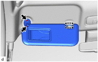
(b) Disengage the guide to remove the visor assembly LH.
33. REMOVE VISOR ASSEMBLY RH
HINT:
Use the same procedure as for the LH side.
34. REMOVE VISOR HOLDER
HINT:
Use the same procedures for the opposite side.
(a) Turn the visor holder clockwise approximately 45° to remove it as shown in the illustration.
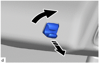
 | Turn |
 | Remove in this Direction |
(b) Disengage the claws to remove the base as shown in the illustration.
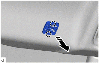
 | Remove in this Direction |
35. REMOVE ASSIST GRIP COVER
HINT:
Use the same procedure for all assist grip sub-assemblies.
| (a) Insert SST into the cutout of the assist grip cover as shown in the illustration. SST: 09813-00010 NOTICE: To prevent the assist grip sub-assembly from being damaged, make sure to insert SST straight into the cutout. |
|
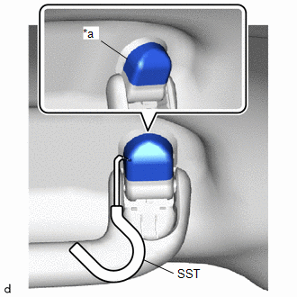
(b) Pull SST to disengage the claw as shown in the illustration.
NOTICE:
To prevent the assist grip sub-assembly from being damaged, make sure to only pull SST as shown in the illustration.
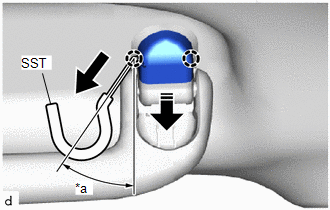
| *a | 30 to 45° |
 | Pull |
 | Remove in this Direction |
(c) Remove the assist grip cover as shown in the illustration.
HINT:
Use the same procedures for the opposite side.
36. REMOVE ASSIST GRIP SUB-ASSEMBLY
HINT:
Use the same procedures for the opposite side.
(a) Disengage the clips to remove the assist grip sub-assembly as shown in the illustration.
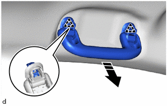
 | Remove in this Direction |
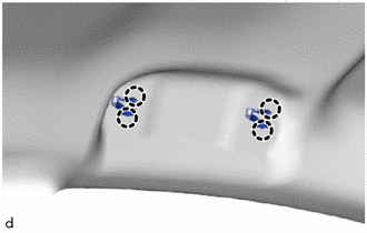
| (b) Disengage the claws to remove the 2 clips from the vehicle body. |
|
37. REMOVE MAP LIGHT ASSEMBLY
Click here

38. REMOVE NO. 1 ROOM LIGHT ASSEMBLY
Click here

39. REMOVE RAIN SENSOR COVER
Click here

40. REMOVE INNER REAR VIEW MIRROR STAY HOLDER COVER (w/o Pre-collision System)
Click here

41. REMOVE NO. 2 FORWARD RECOGNITION COVER (w/ Pre-collision System)
Click here

42. REMOVE NO. 1 FORWARD RECOGNITION COVER (w/ Pre-collision System)
Click here

43. REMOVE ROOF HEADLINING
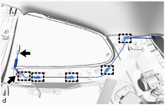
(a) for Front Pillar LH Side:
| (1) Disconnect the 2 connectors. |
|
(2) Disengage the clamps.
(b) for Front Pillar RH Side:
| (1) Disconnect the connector. |
|
(2) Disengage the clamps.
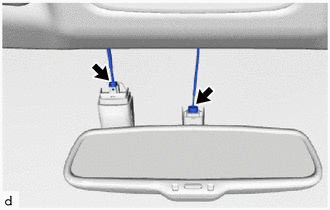
(c) for Windshield Glass Side:
(1) w/o Pre-collision System:
-
Disconnect the 2 connectors.
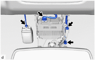
(2) w/ Pre-collision System:
-
Disconnect the 4 connectors.
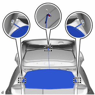
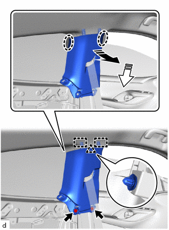
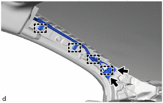
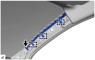
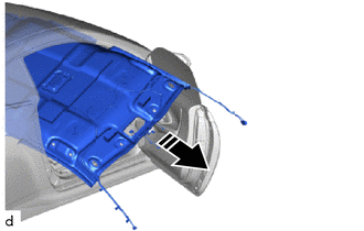
(d) for Rear Pillar RH Side:
| (1) Disconnect the connector. |
|
(2) Remove the bolt.
(3) Disengage the clamps.
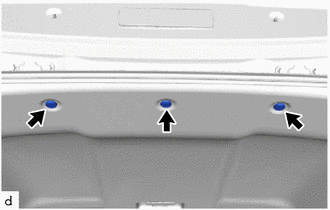
| (e) Remove the 3 clips. |
|
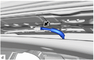
| (f) Disconnect the connector. |
|
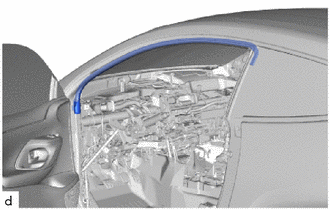
(g) Turn the roof headlining diagonally and bend slightly to remove it from the passenger door as shown in the illustration.
 | Remove in this Direction |
NOTICE:
- Make sure that wrinkles do not form in the roof headlining during removal.
- Make sure that the roof headlining does not get caught on anything as it may become bent or damaged.
- Do not damage the roof headlining or vehicle interior.
 Components
COMPONENTS ILLUSTRATION
*1 NO. 2 HEATER TO REGISTER DUCT SUB-ASSEMBLY *2 PACKAGE TRAY TRIM PANEL ASSEMBLY *3 DECK BOARD ASSEMBLY *4 DECK FLOOR BOX RH *5 DECK FLOOR BOX LH *6 FRONT DOOR OPENING TRIM WEATHERSTRIP LH *7 FRONT DOOR OPENING TRIM WEATHERSTRIP RH - - ILLUSTRATION
*1 LAP BELT OUTER ANCHOR COVER *2 FRONT SEAT OUTER BELT ASSEMBLY LH *3 FRONT SEAT OUTER BELT ASSEMBLY RH *4 REAR SEATBACK HINGE SUB-ASSEMBLY LH *5 REAR SEATBACK HINGE SUB-ASSEMBLY RH *6 QUARTER TRIM PANEL ASSEMBLY LH *7 QUARTER TRIM PANEL ASSEMBLY RH *8 CENTER PILLAR UPPER GARNISH LH *9 CENTER PILLAR UPPER GARNISH RH *10 DECK TRIM REAR COVER *11 DECK TRIM SIDE PANEL ASSEMBLY LH *12 DECK TRIM SIDE PANEL ASSEMBLY RH *13 REAR SEAT OUTER BELT ASSEMBLY LH *14 REAR SEAT OUTER BELT ASSEMBLY RH *15 INNER ROOF SIDE GARNISH LH *16 INNER ROOF SIDE GARNISH RH *17 ROOF SIDE INNER GARNISH LH *18 ROOF SIDE INNER GARNISH RH *19 NO...
 Disassembly
DISASSEMBLY PROCEDURE 1. REMOVE ACTIVE NOISE CONTROL MICROPHONE (w/ Active Noise Control System) Click here
2. REMOVE ROOF HEADLINING HOLDER COVER (w/ Active Noise Control System) HINT: Use the same procedure for the opposite side...
Other information:
Toyota Yaris XP210 (2020-2026) Reapir and Service Manual: Removal
REMOVAL CAUTION / NOTICE / HINT The necessary procedures (adjustment, calibration, initialization, or registration) that must be performed after parts are removed, installed, or replaced during the engine assembly removal/installation are shown below...
Toyota Yaris XP210 (2020-2026) Reapir and Service Manual: Removal
REMOVAL CAUTION / NOTICE / HINT The necessary procedures (adjustment, calibration, initialization, or registration) that must be performed after parts are removed and installed, or replaced during front lower ball joint assembly removal/installation are shown below...
Categories
- Manuals Home
- Toyota Yaris Owners Manual
- Toyota Yaris Service Manual
- Headlights
- G16e-gts (engine Mechanical)
- Removal
- New on site
- Most important about car
Supplemental Restraint System (SRS) Precautions
The front and side supplemental restraint systems (SRS) include different types of air bags. Please verify the different types of air bags which are equipped on your vehicle by locating the “SRS AIRBAG” location indicators. These indicators are visible in the area where the air bags are installed.
The air bags are installed in the following locations:
The steering wheel hub (driver air bag) The front passenger dashboard (front passenger air bag) The outboard sides of the front seatbacks (side air bags) The front and rear window pillars, and the roof edge along both sides (curtain air bags)