Toyota Yaris: Engine Assembly / Removal
REMOVAL
CAUTION / NOTICE / HINT
The necessary procedures (adjustment, calibration, initialization, or registration) that must be performed after parts are removed, installed, or replaced during the engine assembly removal/installation are shown below.
Necessary Procedure After Parts Removed/Installed/Replaced| Replaced Part or Performed Procedure | Necessary Procedure | Effect/Inoperative Function when Necessary Procedure not Performed | Link |
|---|---|---|---|
| Inspection After Repair |
|
|
| Front wheel alignment adjustment | ECU Data Initialization | Active torque split AWD system |
|
| Calibration |
|
|


CAUTION:
-
Because the weight of the engine with transaxle assembly is extremely heavy, make sure to follow the work procedures described in the repair manual.
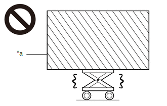
*a
Heavy object exceeding the capacity of the engine lifter
- If work is not performed according to the procedures described in the repair manual, there is a danger that the engine lifter could drop and components could fall down.
-
Do not touch the engine or exhaust manifold converter sub-assembly when they are hot.
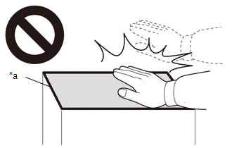
*a
High temperature areas
- Touching the engine or exhaust manifold converter sub-assembly when they are hot could result in burns.
-
Never perform work on fuel system components near any possible ignition sources.
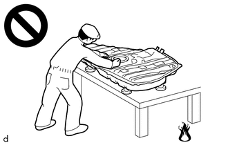
- Vaporized fuel could ignite, resulting in a serious accident.
-
Do not perform work on fuel system components without first disconnecting the cable from the negative (-) auxiliary battery terminal.
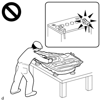
- Sparks could cause vaporized fuel to ignite, resulting in a serious accident.
NOTICE:
This procedure includes the removal of small-head bolts. Refer to Small-Head Bolts of Basic Repair Hint to identify the small-head bolts.
Click here

HINT:
When the cable is disconnected / reconnected to the auxiliary battery terminal, systems temporarily stop operating. However, each system has a function that completes learning the first time the system is used.
-
Learning completes when vehicle is driven
Effect/Inoperative Function When Necessary Procedures are not Performed
Necessary Procedures
Link
Lane tracing assist system
Drive the vehicle straight ahead at 35 km/h (22 mph) or more for 5 second or more.

Pre-collision system
Stop and start system
Drive the vehicle until stop and start control is permitted (approximately 5 to 60 minutes)

-
Learning completes when vehicle is operated normally
Effect/Inoperative Function When Necessary Procedures are not Performed
Necessary Procedures
Link
Power door lock control system
- Back door opener
Perform door unlock operation with door control switch or electrical key transmitter sub-assembly switch.

Air conditioning system
After the ignition switch is turned to ON, the servo motor standard position is recognized.
-
PROCEDURE
1. PRECAUTION
NOTICE:
After turning the engine switch off, waiting time may be required before disconnecting the cable from the negative (-) auxiliary battery terminal. Therefore, make sure to read the disconnecting the cable from the negative (-) auxiliary battery terminal notices before proceeding with work.
Click here

2. RECOVER REFRIGERANT FROM REFRIGERATION SYSTEM
Click here

3. DISCHARGE FUEL SYSTEM PRESSURE
Click here

4. DISCONNECT CABLE FROM NEGATIVE AUXILIARY BATTERY TERMINAL
Click here

5. ALIGN FRONT WHEELS FACING STRAIGHT AHEAD
6. REMOVE FRONT WHEELS
Click here

7. REMOVE NO. 1 ENGINE UNDER COVER ASSEMBLY
Click here

8. REMOVE ENGINE UNDER COVER RH
Click here

9. REMOVE ENGINE UNDER COVER LH
Click here

10. REMOVE CENTER NO. 4 ENGINE UNDER COVER
Click here

11. SEPARATE FRONT FENDER LINER LH
Click here

12. SEPARATE FRONT FENDER LINER RH
Click here

13. DRAIN ENGINE OIL
Click here

14. DRAIN ENGINE COOLANT
Click here

15. DRAIN MANUAL TRANSAXLE OIL
Click here

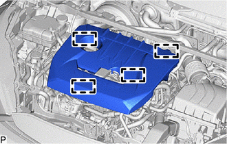
16. REMOVE NO. 1 ENGINE COVER SUB-ASSEMBLY
| (a) Disengage the 4 clamps and remove the No. 1 engine cover sub-assembly. NOTICE: Attempting to disengage both front and rear clips at the same time may cause the No. 1 engine cover sub-assembly to break. |
|
17. REMOVE WINDSHIELD WIPER MOTOR AND LINK
Click here

18. REMOVE NO. 1 FRONT VENTILATOR SEAL
Click here

19. REMOVE WATER GUARD PLATE RH
Click here

20. REMOVE OUTER COWL TOP PANEL SUB-ASSEMBLY
Click here

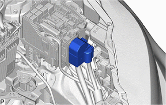
21. REMOVE AIR CLEANER ASSEMBLY
| (a) Disconnect the vacuum switching valve connector. |
|
(b) Disengage the clamp from the air cleaner cap sub-assembly.
| (c) Disconnect the mass air flow meter connector. |
|
(d) Disengage the clamp from the air cleaner cap sub-assembly.
| (e) Remove the 2 clips. |
|
| (f) Disconnect the vacuum transmitting hose. |
|
(g) Disengage the clamp from the intake air pipe.
(h) Disconnect the vacuum hose assy.
(i) Loosen the hose clamp.
(j) Remove the air cleaner assembly.
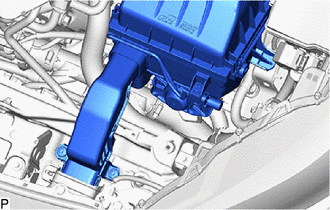
22. REMOVE AIR CLEANER BRACKET
| (a) Disengage the clamp from the air cleaner bracket. |
|
(b) Remove the 2 bolts and air cleaner bracket from the vehicle.
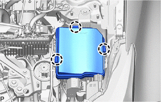
23. REMOVE NO. 1 RELAY BLOCK COVER
| (a) Remove the 3 claws and No. 1 relay block cover from the engine room relay block. |
|
24. REMOVE JUNKTION BLOCK COVER
| (a) Remove the junktion block cover. |
|
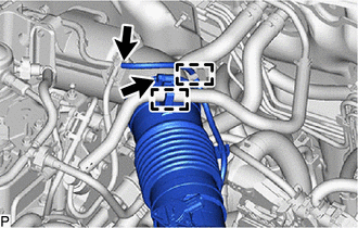
25. DISCONNECT WIRE HARNESS
| (a) Disengage the clamp to separate the engine wire from the vehicle. |
|
(b) Remove the 2 bolts to separate the engine wire from the vehicle.
| (c) Disengage the clamp to separate the engine wire from the vehicle. |
|
| (d) Remove the 2 nuts. |
|
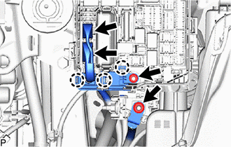
(e) Disconnect the 3 connectors from the engine room relay block.
(f) Disengage the 2 claws to separate the engine wire from the engine room relay block.
26. DISCONNECT NO. 1 RADIATOR HOSE
| (a) Slide the clip and disconnect the No. 1 radiator hose from the water outlet. |
|
27. DISCONNECT NO. 2 RADIATOR HOSE
| (a) Slide the clip and disconnect the No. 2 radiator hose from the water inlet with thermostat sub-assembly. |
|
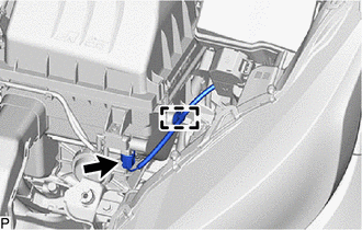
28. REMOVE NO. 2 AIR TUBE
| (a) Loosen the 2 hose clamps. |
|
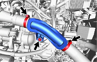
(b) Remove the bolt and remove the No. 2 air tube.
29. REMOVE ECM
Click here

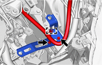
30. DISCONNECT TRANSMISSION CONTROL CABLE ASSEMBLY
| (a) Remove the 2 clips A to disconnect the transmission control cable assembly from the manual transaxle assembly. |
|
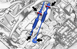
(b) Remove the 2 clips B to disconnect the transmission control cable assembly from control cable bracket assembly.
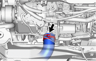
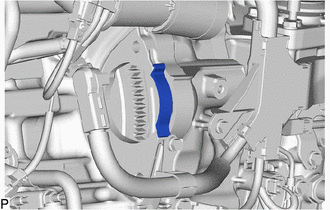
31. DISCONNECT UNION TO CONNECTOR TUBE HOSE
Click here

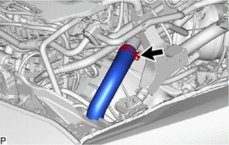
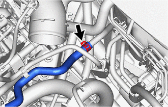
32. REMOVE NO. 1 WATER BY-PASS HOSE
| (a) Slide the clip and disconnect the No. 1 water by-pass hose from the No. 4 water by-pass pipe. |
|
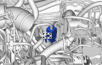
33. REMOVE NO. 2 WATER BY-PASS HOSE
| (a) Slide the clip and disconnect the No. 2 water by-pass hose from the No. 4 water by-pass pipe. |
|
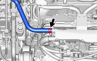
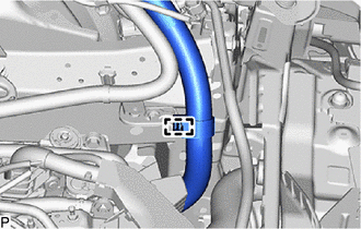
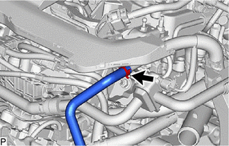
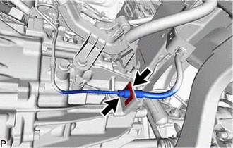
34. DISCONNECT NO. 1 FUEL VAPOR FEED HOSE
| (a) Slide the clip and disconnect the No. 1 fuel vapor hose from the fuel tank to canister tube. |
|
35. DISCONNECT OUTLET HEATER WATER HOSE
Click here

36. DISCONNECT INLET HEATER WATER HOSE
Click here

37. DISCONNECT FUEL TUBE SUB-ASSEMBLY
| (a) Remove the No. 1 fuel pipe clamp for the fuel tube sub-assembly. |
|
| (b) Disconnect the fuel tube sub-assembly from the fuel pipe. Click here
|
|

38. DISCONNECT SUCTION HOSE SUB-ASSEMBLY
Click here

39. DISCONNECT NO. 1 COOLER REFRIGERANT DISCHARGE HOSE
Click here

40. SECURE STEERING WHEEL ASSEMBLY
Click here

41. REMOVE COLUMN HOLE COVER SILENCER SHEET
Click here

42. DISCONNECT NO. 2 STEERING INTERMEDIATE SHAFT ASSEMBLY
Click here

43. REMOVE FRONT DRIVE SHAFT ASSEMBLY
Click here

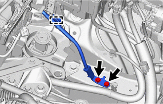
44. DISCONNECT NO. 1 CLUTCH HOSE
| (a) Using a 10 mm union nut wrench, disconnect the bleeder clutch release tube from the No. 1 clutch hose. |
|
(b) Remove the clip and disconnect the No. 1 clutch hose from the clutch flexible hose bracket.
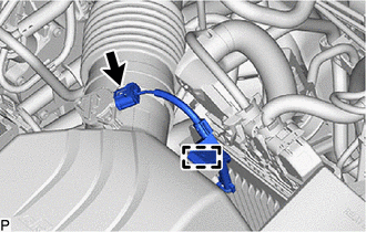
45. REMOVE NO. 1 AIR TUBE
| (a) Remove tha 2 bolts. |
|
(b) Lossen the 2 hose clamps and remove the No. 1 air tube.
46. REMOVE ENGINE ASSEMBLY WITH TRANSAXLE
(a) Set the engine assembly with transaxle on an engine lifter.
NOTICE:
- Using height adjustment attachments and plate lift attachments, keep the engine assembly with transaxle and front suspension crossmember sub-assembly level.
- Do not perform any procedures while the engine assembly is suspended because doing so may cause the engine assembly to drop, resulting in injury. However, the engine assembly needs to be suspended when it is installed to or removed from an engine stand.
- To prevent the engine assembly from unexpectedly moving, securely support the engine assembly until it is secured to an engine stand.
- To prevent the oil pan sub-assembly from deforming, do not place any attachments under the oil pan sub-assembly of the engine assembly with transaxle.
| (b) Remove the 3 bolts and separate the engine mounting insulator sub-assembly RH from the engine mounting bracket RH. |
|
| (c) Remove the 4 bolts and separate the engine mounting insulator LH from the hybrid vehicle transaxle assembly. |
|
| (d) Remove the 8 bolts to separate the front suspension crossmember sub-assembly from the vehicle. |
|
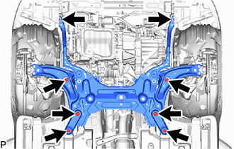
(e) Operate the engine lifter and remove the engine assembly with transaxle from the vehicle.
NOTICE:
- Make sure that the engine assembly with transaxle is clear of all wiring and hoses.
- While lowering the engine assembly with transaxle from the vehicle, do not allow it to contact the vehicle.
47. INSTALL ENGINE HANGERS
(a) Install the No. 1 engine hanger and No. 2 engine hanger with the 4 bolts as shown in the illustration.
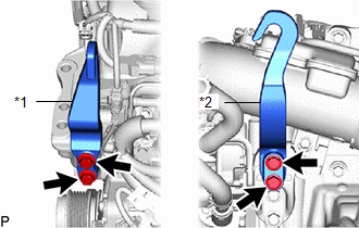
| *1 | No. 1 Engine Hanger |
| *2 | No. 2 Engine Hanger |
 | Bolt |
Torque:
43 N·m {438 kgf·cm, 32 ft·lbf}
| No. 1 Engine Hanger | 12281-25030 12281-25040 |
| No. 2 Engine Hanger | 12282-18010 12282-18020 |
| Bolt | 91552-F1045 91552-F1060 |
(b) Using an engine sling device and engine lift, secure the engine assembly with transaxle.
NOTICE:
- Pay attention to the angle of the sling device as the engine assembly or No. 1 engine hanger and No. 2 engine hanger may be damaged or deformed if the angle is incorrect.
- Do not perform any procedures while the engine assembly is suspended because doing so may cause the engine assembly to drop, resulting in injury. However, the engine assembly needs to be suspended when it is installed to or removed from an engine stand.
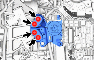
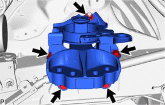
48. REMOVE ENGINE MOUNTING INSULATOR LH
HINT:
Perform this procedure only when replacement of the engine mounting insulator LH is necessary.
| (a) Disengage the clamp from the engine mounting insulator LH. |
|
| (b) Remove the 5 bolts, nut and engine mounting insulator LH from the vehicle. |
|
49. REMOVE RESERVE TANK ASSEMBLY
| (a) Slide the clip and remove the No.3 water by-pass hose from the reserve tank assy. |
|
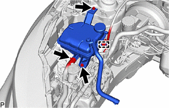
(b) Disengage the clamp and remove the engine wire from the reserve tank assy.
(c) Remove the 2 bolts and remove the reserve tank assy from the vehicle.
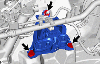
50. REMOVE ENGINE MOUNTING INSULATOR SUB-ASSEMBLY RH
HINT:
Perform this procedure only when replacement of the engine mounting insulator sub-assembly RH is necessary.
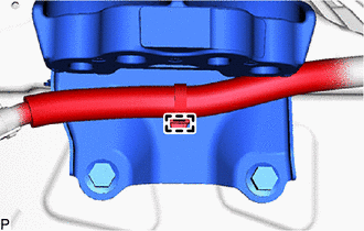
| (a) Remove the clamp and disconnect the air conditioner tube. |
|
| (b) Remove the 2 bolts, nut and engine mounting insulator sub-assembly RH from the vehicle. |
|
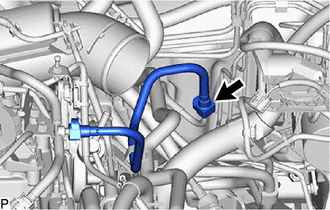
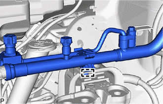
51. REMOVE NO. 1 FUEL VAPOR FEED HOSE
| (a) Disengage the 2 clamps from the engine assembly with transaxle. |
|
(b) Slide the clip and remove the No. 1 fuel vapor feed hose from the engine assembly with transaxle.
52. REMOVE STARTER ASSEMBLY
Click here

53. REMOVE FLYWHEEL HOUSING SIDE COVER
| (a) Remove the flywheel housing side cover from the cylinder block sub-assembly. |
|
54. REMOVE FAN AND GENERATOR V BELT
Click here

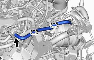
55. REMOVE V-RIBBED BELT TENSIONER ASSEMBLY
| (a) Remove the 2 bolts and V-ribbed belt tensioner assembly from the timing chain cover assembly. |
|

56. REMOVE GENERATOR WITH REGULATOR ASSEMBLY
Click here

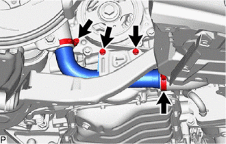
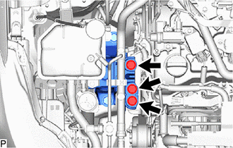
57. REMOVE ENGINE WIRE
| (a) Remove the 4 bolts. |
|
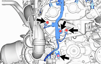
| (b) Remove the 4 bolts. |
|
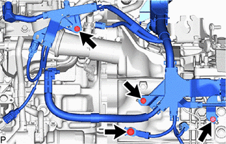
(c) Remove the 2 bolts.
| (d) Remove the 2 bolts. |
|
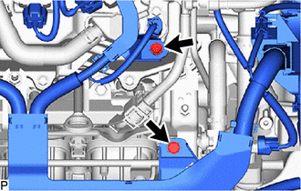
(e) Disconnect all the clamps and connectors and remove the engine wire from the engine assembly with transaxle.
58. REMOVE EXHAUST MANIFOLD CONVERTER SUB-ASSEMBLY
Click here

59. REMOVE PROPELLER SHAFT HEAT INSULATOR
Click here

60. REMOVE MANUAL TRANSAXLE ASSEMBLY
Click here

61. REMOVE COVER AND DISC CLUTCH SET
Click here

62. REMOVE FLYWHEEL SUB-ASSEMBLY
Click here

63. REMOVE NO. 1 CRANKSHAFT POSITION SENSOR PLATE
Click here

64. INSTALL ENGINE ASSEMBLY TO ENGINE STAND
(a) Install the engine assembly to an engine stand.
65. REMOVE ENGINE HANGERS
(a) Remove the 4 bolts, No. 1 engine hanger and No. 2 engine hanger.
 Components
COMPONENTS ILLUSTRATION
*1 NO. 1 ENGINE UNDER COVER ASSEMBLY *2 ENGINE UNDER COVER RH *3 ENGINE UNDER COVER LH *4 CENTER NO. 4 ENGINE UNDER COVER
N*m (kgf*cm, ft...
 Installation
INSTALLATION CAUTION / NOTICE / HINT CAUTION: The engine assembly with transaxle is very heavy. Be sure to follow the procedure described in the repair manual, or the engine lifter may suddenly drop...
Other information:
Toyota Yaris XP210 (2020-2026) Reapir and Service Manual: Freeze Frame Data
FREEZE FRAME DATA FREEZE FRAME DATA (a) Using the GTS, check the vehicle condition (ECU, sensor) when the brake system operates or a DTC is output. CHECK FREEZE FRAME DATA WHEN DTC WAS STORED HINT: Freeze frame data is stored when a DTC is output. Once freeze frame data is stored when a DTC is output, it is not updated or cleared until the DTC is cleared...
Toyota Yaris XP210 (2020-2026) Reapir and Service Manual: Turbocharger/Supercharger Boost Sensor "A" Circuit Short to Ground (P023511)
DESCRIPTION The internal sensor in the No. 2 turbo pressure sensor detects the air outlet duct internal pressure as a voltage. DTC No. Detection Item DTC Detection Condition Trouble Area MIL Note P023511 Turbocharger/Supercharger Boost Sensor "A" Circuit Short to Ground The output voltage from the No...
Categories
- Manuals Home
- Toyota Yaris Owners Manual
- Toyota Yaris Service Manual
- How to use USB mode
- Key Battery Replacement
- Engine Start Function When Key Battery is Dead
- New on site
- Most important about car
Turning the Engine Off
Stop the vehicle completely. Manual transaxle: Shift into neutral and set the parking brake.Automatic transaxle: Shift the selector lever to the P position and set the parking brake.
Press the push button start to turn off the engine. The ignition position is off.