Toyota Yaris: Engine Assembly / Installation
INSTALLATION
CAUTION / NOTICE / HINT
CAUTION:
The engine assembly with transaxle is very heavy. Be sure to follow the procedure described in the repair manual, or the engine lifter may suddenly drop.
NOTICE:
This procedure includes the removal of small-head bolts. Refer to Small-Head Bolts of Basic Repair Hint to identify the small-head bolts.
Click here

HINT:
Perform "Inspection After Repair" after replacing the engine assembly.
Click here

PROCEDURE
1. INSTALL ENGINE HANGER
Click here

2. REMOVE ENGINE FROM ENGINE STAND
(a) Remove the engine assembly from the engine stand.
3. INSTALL NO. 1 CRANKSHAFT POSITION SENSOR PLATE
Click here

4. INSTALL FLYWHEEL SUB-ASSEMBLY
Click here

5. INSTALL COVER AND DISC CLUTCH SET
Click here

6. INSTALL MANUAL TRANSAXLE ASSEMBLY
Click here

7. INSTALL PROPELLER SHAFT HEAT INSULATOR
Click here

8. INSTALL EXHAUST MANIFOLD CONVERTER SUB-ASSEMBLY
Click here

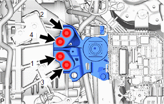
9. INSTALL ENGINE WIRE
(a) Connect all the connectors and clamps, and install the engine wire to the engine assembly with transaxle.
| (b) Install the 2 bolts. Torque: 10 N·m {102 kgf·cm, 7 ft·lbf} |
|
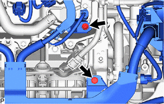
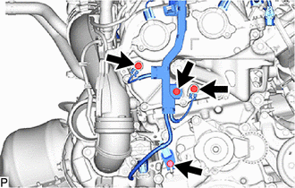
| (c) Install the 4 bolts. Torque: Bolt (A) : 10 N·m {102 kgf·cm, 7 ft·lbf} Bolt (B) : 20 N·m {204 kgf·cm, 15 ft·lbf} |
|
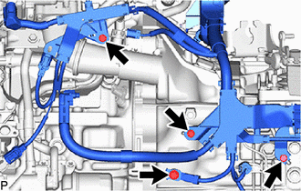
| (d) Install the 4 bolts. Torque: 10 N·m {102 kgf·cm, 7 ft·lbf} |
|
10. INSTALL GENERATOR WITH REGULATOR ASSEMBLY
Click here

11. INSTALL V-RIBBED BELT TENSIONER ASSEMBLY
(a) Install the V-ribbed belt tensioner assembly with the 2 bolts.
Torque:
21 N·m {214 kgf·cm, 15 ft·lbf}
12. INSTALL FAN AND GENERATOR V BELT
Click here

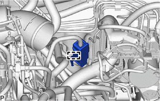
13. INSTALL FLYWHEEL HOUSING SIDE COVER
(a) Install the flywheel housing side cover to the cylinder block sub-assembly.
14. INSTALL STARTER ASSEMBLY
Click here

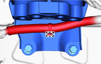
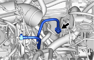
15. INSTALL NO. 1 FUEL VAPOR FEED HOSE
(a) Engage the 2 clamps.
(b) Install the No. 1 fuel vapor feed hose to the purge valve (purge VSV).
16. INSTALL ENGINE MOUNTING INSULATOR SUB-ASSEMBLY RH
HINT:
Perform this procedure only when replacement of the engine mounting insulator sub-assembly RH is necessary.
| (a) Temporarily install the engine mounting insulator sub-assembly RH to the vehicle. |
|
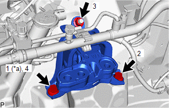
(b) Install the 2 bolts and nut in the order shown in the illustration.
Torque:
72 N·m {734 kgf·cm, 53 ft·lbf}
(c) Connect the air conditioner tube with the clamp.
17. INSTALL RESERVE TANK ASSEMBLY
(a) Install the 2 bplts and reserve tank assembly to the vehicle.
Torque:
4.0 N·m {41 kgf·cm, 35 in·lbf}
(b) Engage the clamp.
(c) Connect the No. 3 water by-pass hose to the reserve tank assembly and slide the clip to secure it.
18. INSTALL ENGINE MOUNTING INSULATOR LH
HINT:
Perform this procedure only when replacement of the engine mounting insulator LH is necessary.
| (a) Temporarily install the engine mounting insulator LH to the vehicle. |
|
(b) Install the 5. bolts and nut in the order shown in the illustration.
Torque:
42 N·m {428 kgf·cm, 31 ft·lbf}
| (c) Engage the clamp. |
|
19. REMOVE ENGINE HANGER
Click here

20. INSTALL ENGINE ASSEMBLY WITH TRANSAXLE
(a) Using height adjustment attachments and plate lift attachments to keep the engine assembly with transaxle and front suspension crossmember sub-assembly level, set an engine lifter underneath the engine assembly with transaxle and front suspension crossmember sub-assembly.
NOTICE:
- Using height adjustment attachments and plate lift attachments, keep the engine assembly with transaxle horizontal.
- Do not perform any procedures while the engine assembly is suspended because doing so may cause the engine assembly to drop, resulting in injury. However, the engine assembly needs to be suspended when it is installed to or removed from an engine stand.
- To prevent the oil pan sub-assembly from deforming, do not place any attachments under the oil pan sub-assembly of the engine assembly with transaxle.
(b) Operate the engine lifter and install the engine assembly with transaxle to the vehicle.
CAUTION:
Do not raise the engine assembly with transaxle more than necessary. If the engine is raised excessively, the vehicle may also be lifted up.
NOTICE:
- Make sure that the engine assembly with transaxle is clear of all wiring and hoses.
- While raising the engine assembly with transaxle into the vehicle, do not allow it to contact the vehicle.
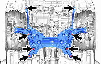
| (c) Connect the front suspension crossmember sub-assembly to the vehicle with the 8 bolts. Torque: 95 N·m {969 kgf·cm, 70 ft·lbf} |
|
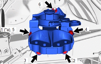
| (d) Install the engine mounting insulator sub-assembly RH to the engine mounting bracket RH with the 3 bolts in the order shown illustration. Torque: 72 N·m {734 kgf·cm, 53 ft·lbf} |
|
| (e) Install the engine mounting insulator LH to the engine mounting bracket LH with the 4 bolts in the order shown illustration. Torque: 52 N·m {530 kgf·cm, 38 ft·lbf} |
|
21. INSTALL NO. 1 CLUTCH HOSE
| (a) Connect the No. 1 clutch hose to the clutch flexible hose bracket with a new clip. |
|
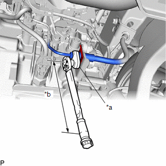
(b) Using a 10 mm union nut wrench, connect the bleeder clutch release tube to the No. 1 clutch hose.
Torque:
Specified tightening torque :
15.2 N·m {155 kgf·cm, 11 ft·lbf}
HINT:
-
Calculate the torque wrench reading when changing the fulcrum length of the torque wrench.
Click here

- When using a 10 mm union nut wrench (fulcrum length of 22 mm (0.866 in.)) + torque wrench (fulcrum length of 162 mm (6.38 in.)): 13.4 N*m (137 kgf*cm, 10 ft.*lbf)
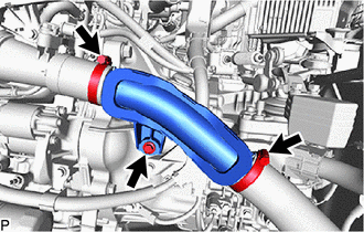
22. INSTALL NO. 1 AIR TUBE
(a) Install the No. 1 air tube with the 2 bolts.
Torque:
7.0 N·m {71 kgf·cm, 62 in·lbf}
(b) Tighten the 2 hose clamp.
Torque:
6.0 N·m {61 kgf·cm, 53 in·lbf}
23. INSTALL DRIVE SHAFT ASSEMBLY
Click here

24. INSTALL PROPELLER WITH CENTER BEARING SHAFT ASSEMBLY
Click here

25. CONNECT NO. 2 STEERING INTERMEDIATE SHAFT ASSEMBLY
Click here

26. INSTALL COLUMN HOLE COVER SILENCER SHEET
Click here

27. CONNECT NO. 1 COOLER REFRIGERANT DISCHARGE HOSE
Click here

28. CONNECT SUCTION HOSE SUB-ASSEMBLY
Click here

29. CONNECT FUEL TUBE SUB-ASSEMBLY
| (a) Connect the fuel tube sub-assembly to the fuel pipe. Click here
|
|

| (b) Install the No. 1 fuel pipe clamp to the fuel tube sub-assembly. |
|
30. CONNECT INLET HEATER WATER HOSE
Click here

31. CONNECT OUTLET HEATER WATER HOSE
Click here

32. CONNECT NO. 1 FUEL VAPOR FEED HOSE
(a) Connect the No. 1 fuel vapor feed hose to the fuel tank to canister tube.
33. INSTALL NO. 2 WATER BY-PASS HOSE
(a) Connect the No. 2 water by-pass hose to the No. 4 water by-pass pipe and slide the clip to secure it.
34. INSTALL NO. 1 WATER BY-PASS HOSE
(a) Connect the No. 1 water by-pass hose to the No. 4 water by-pass pipe and slide the clip to secure it.
35. CONNECT UNION TO CONNECTOR TUBE HOSE
Click here

36. CONNECT TRANSMISSION CONTROL CABLE ASSEMBLY
| (a) Install the transmission control cable assembly to the control cable bracket assembly with 2 new clips (B). NOTICE: Make sure that the paint marks on the transmission control cable assembly are aligned with the slits in the control cable bracket assembly before installing the clips. |
|
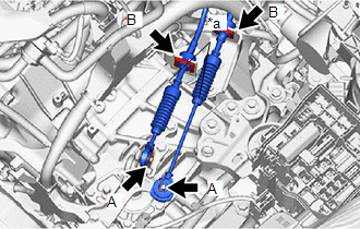
(b) Connect the transmission control cable assembly to the manual transaxle assembly with the 2 clips (A).
37. INSTALL ECM
Click here

38. INSTALL NO. 2 AIR TUBE
| (a) Install the No. 2 air hose with the bolt. Torque: 21 N·m {214 kgf·cm, 15 ft·lbf} |
|
(b) Tighten the hose 2 clamps.
Torque:
6.0 N·m {61 kgf·cm, 53 in·lbf}
39. CONNECT NO. 2 RADIATOR HOSE
(a) Connect the No. 2 radiator hose to the radiator assembly and slide the clip to secure it.
40. CONNECT NO. 1 RADIATOR HOSE
(a) Connect the No. 1 radiator hose to the water outlet and slide the clip to secure it.
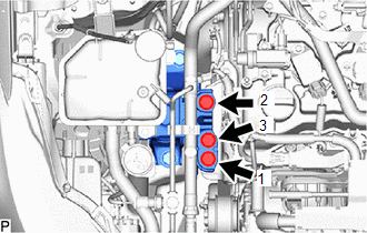
41. CONNECT ENGINE WIRE
(a) Engage the 2 claws to the engine room relay block.
(b) Connect the 3 connectors to the engine room relay block.
(c) Install the 2 nut.
Torque:
Nut (A) :
10 N·m {102 kgf·cm, 7 ft·lbf}
Nut (B) :
7.6 N·m {77 kgf·cm, 67 in·lbf}
(d) Engage the clamp to connect the engine wire to the vehicle.
(e) Connect the engine wire to the vehicle with the 2 bolts.
Torque:
10 N·m {102 kgf·cm, 7 ft·lbf}
42. INSTALL JUNKTION BLOCK COVER
(a) Install the junktion block cover.
43. INSTALL NO. 1 RELAY BLOCK COVER
(a) Install the No. 1 relay block cover.
44. INSTALL AIR CLEANER BRACKET
(a) Install the air cleaner bracket with the 2 bolts.
Torque:
7.0 N·m {71 kgf·cm, 62 in·lbf}
(b) Engage the clamp to the air cleaner bracket.
45. INSTALL AIR CLEANER ASSEMBLY
(a) Install the air cleaner assembly and tighten the hose clamp.
Torque:
3.0 N·m {31 kgf·cm, 27 in·lbf}
(b) Connect the vacuum hose assembly and vacuum transmittinghose.
(c) Install the 2 clips.
(d) Connect the clamp.
(e) Connect the mass air flow meter connector.
(f) Engage the clamp to the air cleaner assembly.
(g) Connect the vacuum switching valve connector.
46. INSTALL OUTER COWL TOP PANEL SUB-ASSEMBLY
Click here

47. INSTALL NO. 1 FRONT VENTILATOR SEAL
Click here

48. INSTALL WATER GUARD PLATE RH
Click here

49. INSTALL WINDSHIELD WIPER MOTOR AND LINK
Click here

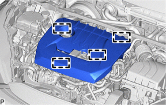
50. INSTALL NO. 1 ENGINE COVER SUB-ASSEMBLY
| (a) Engage the 4 clamps to install the No. 1 engine cover sub-assembly. NOTICE:
|
|
51. INSTALL FRONT FENDER LINER LH
Click here

52. INSTALL FRONT FENDER LINER RH
Click here

53. CONNECT CABLE FROM NEGATIVE AUXILIARY BATTERY TERMINAL
Click here

54. ADD ENGINE OIL
Click here

55. ADD ENGINE COOLANT
Click here

56. ADD MANUAL TRANSAXLE OIL
Click here

57. CHARGE AIR CONDITIONING SYSTEM WITH REFRIGERANT
Click here

58. WARM UP ENGINE
Click here

59. ADJUST TRANSMISSION CONTROL CABLE ASSEMBLY
Click here

60. INSPECT FOR ENGINE OIL LEAK
Click here

61. INSPECT MANUAL TRANSAXLE OIL LEAK
62. INSPECT FOR COOLANT LEAK
Click here

63. INSPECT FOR REFRIGERANT LEAK
Click here

64. INSPECT FOR FUEL LEAK
Click here

65. INSPECT FOR EXHAUST GAS LEAK
Click here

66. CHECK ENGINE OIL LEVEL
Click here

67. INSPECT RADIATOR RESERVE TANK ENGINE COOLANT LEVEL
Click here

68. INSTALL CENTER NO. 4 ENGINE UNDER COVER
Click here

69. INSTALL ENGINE UNDER COVER RH
Click here

70. INSTALL ENGINE UNDER COVER LH
Click here

71. INSTALL NO. 1 ENGINE UNDER COVER ASSEMBLY
Click here

72. INSTALL FRONT WHEELS
Click here

73. ALIGN FRONT WHEELS FACING STRAIGHT AHEAD
74. INSPECT AND ADJUST FRONT WHEEL ALIGNMENT
Click here

75. PERFORM INITIALIZATION
Click here

76. INSPECT IGNITION TIMING
Click here

77. INSPECT ENGINE IDLE SPEED
Click here

78. INSPECT CO/HC
Click here

 Removal
REMOVAL CAUTION / NOTICE / HINT The necessary procedures (adjustment, calibration, initialization, or registration) that must be performed after parts are removed, installed, or replaced during the engine assembly removal/installation are shown below...
 Engine Unit
..
Other information:
Toyota Yaris XP210 (2020-2026) Reapir and Service Manual: Engine Immobiliser System Signal (Some Circuit Quantity, Reported via Serial Data) Invalid (B279986)
DESCRIPTION If there is a communication malfunction between the ECM and ID code box (immobiliser code ECU), or when the communication ID codes do not match, the ECM stores this DTC. DTC No. Detection Item DTC Detection Condition Trouble Area Note B279986 Engine Immobiliser System Signal (Some Circuit Quantity, Reported via Serial Data) Invalid Either of the following conditions is met (1 trip detection logic*): A malfunction is detected in the communication or communication lines between the ECM and ID code box (immobiliser code ECU)...
Toyota Yaris XP210 (2020-2026) Owner's Manual: Rear Window Wiper and Washer (If equipped)
Turn the wiper on by turning the rear wiper/washer switch. Rear Window Washer To spray washer fluid, turn the rear wiper/washer switch to either of the position. After the switch is removed, the washer will stop. If the washer does not work, inspect the fluid level...
Categories
- Manuals Home
- Toyota Yaris Owners Manual
- Toyota Yaris Service Manual
- Immobilizer System
- Diagnostic Trouble Code Chart
- Power Integration No.1 System Missing Message (B235287,B235587,B235787-B235987)
- New on site
- Most important about car
Front Seat Belt Pretensioners
The front seat belt pretensioners are designed to deploy in moderate or severe frontal, near frontal collisions.
In addition, the pretensioners operate when a side collision or a rollover accident is detected. The pretensioners operate differently depending on what types of air bags are equipped. For more details about the seat belt pretensioner operation, refer to the SRS Air Bag Deployment Criteria.