Toyota Yaris: Airbag System / Driver Frontal Stage 1 Deployment Control Circuit Short to Battery (B000112)
DESCRIPTION
| DTC No. | Detection Item | DTC Detection Condition | Trouble Area | Warning Indicate | Test Mode / Check Mode |
|---|---|---|---|---|---|
| B000112 | Driver Frontal Stage 1 Deployment Control Circuit Short to Battery |
|
| Comes on | Applies to check mode |
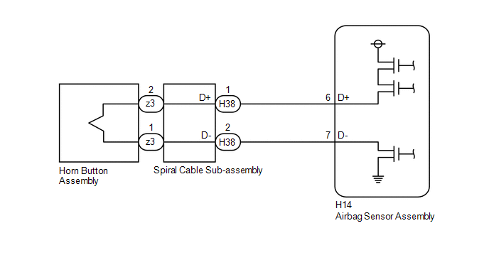
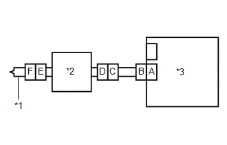
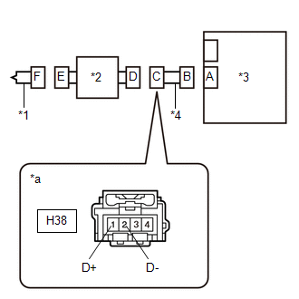
WIRING DIAGRAM
CAUTION / NOTICE / HINT
NOTICE:
After turning the ignition switch off, waiting time may be required before disconnecting the cable from the negative (-) auxiliary battery terminal.
Click here

HINT:
-
To perform the simulation method, select Check Mode with the GTS.
Click here

-
Perform the simulation method while checking the Data List.
Click here

-
When disconnecting and reconnecting the cable to the auxiliary battery terminal, there is an automatic learning function that completes learning when the respective system is used.
Click here

PROCEDURE
| 1. | CHECK CURRENT DTC |
(a) Turn the ignition switch to ON, and wait for at least 60 seconds.
(b) Check for DTCs.
Body Electrical > SRS Airbag > Trouble Codes| Result | Proceed to |
|---|---|
| Current B000112 is output | A |
| History B000112 is output | B |
| B |
 | USE SIMULATION METHOD TO CHECK |
|

| 2. | CHECK CONNECTION OF CONNECTORS |
(a) Turn the ignition switch off.
(b) Disconnect the cable from the negative (-) auxiliary battery terminal.
CAUTION:
Wait at least 60 seconds after disconnecting the cable from the negative (-) auxiliary battery terminal to disable the SRS system.
(c) Check that the connectors are properly connected to the horn button assembly, spiral cable sub-assembly and airbag sensor assembly.
OK:
The connectors are properly connected.
| NG |
 | CONNECT CONNECTORS PROPERLY |
|

| 3. | CHECK CONNECTORS |
| (a) Disconnect the connectors from the horn button assembly, spiral cable sub-assembly and airbag sensor assembly. |
|
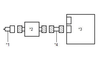
(b) Check that the terminals of the connectors are not deformed or damaged.
OK:
The terminals of the connectors are not deformed or damaged.
(c) Check that the short springs of the activation prevention mechanisms of the wire harness connector and spiral cable sub-assembly connector are not deformed or damaged.
OK:
The short springs are not deformed or damaged.
(d) Check that the spiral cable sub-assembly connector (on the horn button assembly side) is not loose, deformed or damaged.
OK:
The airbag connector locking button is not disengaged, and the claw of the lock is not deformed or damaged.
| NG |
 | REPLACE SPIRAL CABLE SUB-ASSEMBLY OR REPAIR OR REPLACE WIRE HARNESS |
|

| 4. | CLEAR DTC |
| (a) Connect the connectors to the airbag sensor assembly and spiral cable sub-assembly. |
|
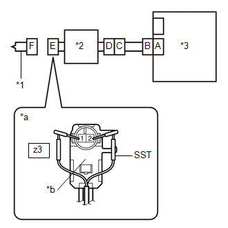
(b) Connect the white wire side of SST (resistance 2.1 Ω) to connector E (light green connector).
CAUTION:
Never connect a tester to the horn button assembly for measurement, as this may lead to a serious injury due to airbag deployment.
NOTICE:
- Do not forcibly insert SST into the terminals of the connector when connecting it.
- Insert SST straight into the terminals of the connector.
SST: 09843-18061
(c) Connect the cable to the negative (-) auxiliary battery terminal.
(d) Turn the ignition switch to ON, and wait for at least 60 seconds.
(e) Clear the DTCs stored in memory.
Body Electrical > SRS Airbag > Clear DTCs(f) Turn the ignition switch off.
|

| 5. | CHECK HORN BUTTON ASSEMBLY |
(a) Turn the ignition switch to ON, and wait for at least 60 seconds.
(b) Check for DTCs.
Body Electrical > SRS Airbag > Trouble Codes| Result | Proceed to |
|---|---|
| B000112 is not output | A |
| B000112 is output | B |
HINT:
Codes other than DTC B000112 may be output at this time, but they are not related to this check.
(c) Turn the ignition switch off.
(d) Disconnect the cable from the negative (-) auxiliary battery terminal.
CAUTION:
Wait at least 60 seconds after disconnecting the cable from the negative (-) auxiliary battery terminal to disable the SRS system.
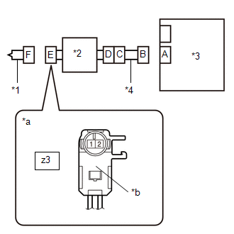
(e) Disconnect SST from connector E.
| A |
 | REPLACE HORN BUTTON ASSEMBLY |
|

| 6. | CHECK DRIVER SEAT AIRBAG SQUIB CIRCUIT |
| (a) Disconnect the connector from the airbag sensor assembly. |
|
(b) Check for a short to B+ in the circuit.
(1) Connect the cable to the negative (-) auxiliary battery terminal.
(2) Turn the ignition switch to ON.
(3) Measure the voltage according to the value(s) in the table below.
Standard Voltage:
| Tester Connection | Switch Condition | Specified Condition |
|---|---|---|
| z3-2 - Body ground | Ignition switch ON | Below 1 V |
| z3-1 - Body ground | Ignition switch ON | Below 1 V |
(4) Turn the ignition switch off.
(5) Disconnect the cable from the negative (-) auxiliary battery terminal.
CAUTION:
Wait at least 60 seconds after disconnecting the cable from the negative (-) auxiliary battery terminal to disable the SRS system.
| NG |
 | GO TO STEP 9 |
|

| 7. | CLEAR DTC |
| (a) Connect the connectors to the horn button assembly and airbag sensor assembly. |
|
(b) Connect the cable to the negative (-) auxiliary battery terminal.
(c) Turn the ignition switch to ON, and wait for at least 60 seconds.
(d) Clear the DTCs stored in memory.
Body Electrical > SRS Airbag > Clear DTCs(e) Turn the ignition switch off.
|

| 8. | CHECK DTC |
(a) Turn the ignition switch to ON, and wait for at least 60 seconds.
(b) Check for DTCs.
Body Electrical > SRS Airbag > Trouble Codes| Result | Proceed to |
|---|---|
| B000112 is not output | A |
| B000112 is output | B |
HINT:
Codes other than DTC B000112 may be output at this time, but they are not related to this check.
| A |
 | USE SIMULATION METHOD TO CHECK |
| B |
 | REPLACE AIRBAG SENSOR ASSEMBLY |
| 9. | CHECK WIRE HARNESS (SHORT TO B+) |
| (a) Disconnect the connector from the spiral cable sub-assembly. |
|
(b) Connect the cable to the negative (-) auxiliary battery terminal.
(c) Turn the ignition switch to ON.
(d) Measure the voltage according to the value(s) in the table below.
Standard Voltage:
| Tester Connection | Switch Condition | Specified Condition |
|---|---|---|
| H38-1 (D+) - Body ground | Ignition switch ON | Below 1 V |
| H38-2 (D-) - Body ground | Ignition switch ON | Below 1 V |
(e) Turn the ignition switch off.
(f) Disconnect the cable from the negative (-) auxiliary battery terminal.
CAUTION:
Wait at least 60 seconds after disconnecting the cable from the negative (-) auxiliary battery terminal to disable the SRS system.
| OK |
 | REPLACE SPIRAL CABLE SUB-ASSEMBLY |
| NG |
 | REPAIR OR REPLACE HARNESS OR CONNECTOR |
 Driver Frontal Stage 1 Deployment Control Circuit Short to Ground (B000111)
DESCRIPTION DTC No. Detection Item DTC Detection Condition Trouble Area Warning Indicate Test Mode / Check Mode B000111 Driver Frontal Stage 1 Deployment Control Circuit Short to Ground
The airbag sensor assembly detects a short to ground in the driver seat airbag squib circuit for 0...
 Driver Frontal Stage 1 Deployment Control Circuit Open (B000113)
DESCRIPTION DTC No. Detection Item DTC Detection Condition Trouble Area Warning Indicate Test Mode / Check Mode B000113 Driver Frontal Stage 1 Deployment Control Circuit Open
The airbag sensor assembly detects an open in the driver seat airbag squib circuit for 2 seconds
Spiral cable sub-assembly malfunction
Horn button assembly malfunction
Airbag sensor assembly malfunction
Harness or connector
Spiral cable sub-assembly
Horn button assembly
Airbag sensor assembly
Comes on Applies to check mode WIRING DIAGRAM
CAUTION / NOTICE / HINT NOTICE: After turning the ignition switch off, waiting time may be required before disconnecting the cable from the negative (-) auxiliary battery terminal...
Other information:
Toyota Yaris XP210 (2020-2024) Reapir and Service Manual: Components
COMPONENTS ILLUSTRATION *1 NO. 1 VALVE ROCKER ARM SUB-ASSEMBLY *2 VALVE LASH ADJUSTER ASSEMBLY *3 VALVE STEM CAP *4 CYLINDER HEAD SUB-ASSEMBLY *5 CYLINDER HEAD GASKET *6 CYLINDER HEAD SET BOLT *7 NO. 1 CAMSHAFT BEARING CAP - - Tightening torque for "Major areas involving basic vehicle performance such as moving/turning/stopping" : N*m (kgf*cm, ft...
Toyota Yaris XP210 (2020-2024) Reapir and Service Manual: Fuel Sender Circuit Open (B150013,B150113)
DESCRIPTION The fuel sender gauge assembly is connected to the combination meter assembly via direct line. If there is an open or short in the direct line, the combination meter assembly stores DTC B150013. The fuel sender gauge assembly and No. 2 fuel sender gauge assembly are connected to the combination meter assembly via direct line...
Categories
- Manuals Home
- Toyota Yaris Owners Manual
- Toyota Yaris Service Manual
- Fuel Gauge
- Fuse Panel Description
- Operating the Radio
- New on site
- Most important about car
Fuel-Filler Lid and Cap
WARNING
When removing the fuel-filler cap, loosen the cap slightly and wait for any hissing to stop, then remove it
Fuel spray is dangerous. Fuel can burn skin and eyes and cause illness if ingested. Fuel spray is released when there is pressure in the fuel tank and the fuel-filler cap is removed too quickly.