Toyota Yaris: Airbag System / Driver Frontal Stage 1 Deployment Control Circuit Short to Ground (B000111)
DESCRIPTION
| DTC No. | Detection Item | DTC Detection Condition | Trouble Area | Warning Indicate | Test Mode / Check Mode |
|---|---|---|---|---|---|
| B000111 | Driver Frontal Stage 1 Deployment Control Circuit Short to Ground |
|
| Comes on | Applies to check mode |
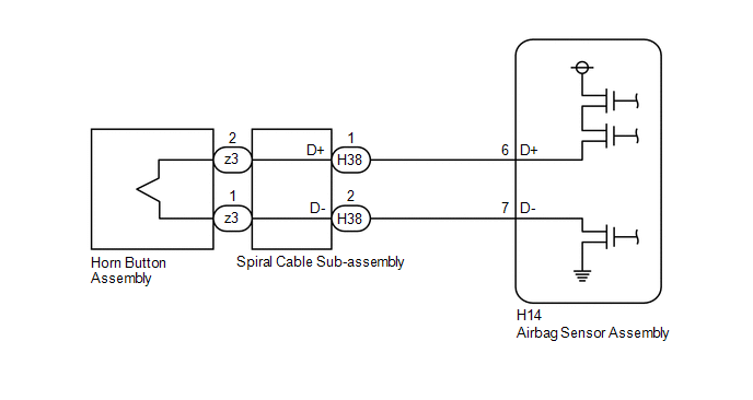
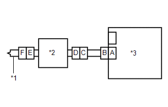
WIRING DIAGRAM
CAUTION / NOTICE / HINT
NOTICE:
After turning the ignition switch off, waiting time may be required before disconnecting the cable from the negative (-) auxiliary battery terminal.
Click here

HINT:
-
To perform the simulation method, select Check Mode with the GTS.
Click here

-
Perform the simulation method while checking the Data List.
Click here

-
When disconnecting and reconnecting the cable to the auxiliary battery terminal, there is an automatic learning function that completes learning when the respective system is used.
Click here

PROCEDURE
| 1. | CHECK CURRENT DTC |
(a) Turn the ignition switch to ON, and wait for at least 60 seconds.
(b) Check for DTCs.
Body Electrical > SRS Airbag > Trouble Codes| Result | Proceed to |
|---|---|
| Current B000111 is output | A |
| History B000111 is output | B |
| B |
 | USE SIMULATION METHOD TO CHECK |
|

| 2. | CHECK CONNECTION OF CONNECTORS |
(a) Turn the ignition switch off.
(b) Disconnect the cable from the negative (-) auxiliary battery terminal.
CAUTION:
Wait at least 60 seconds after disconnecting the cable from the negative (-) auxiliary battery terminal to disable the SRS system.
(c) Check that the connectors are properly connected to the horn button assembly, spiral cable sub-assembly and airbag sensor assembly.
OK:
The connectors are properly connected.
| NG |
 | CONNECT CONNECTORS PROPERLY |
|

| 3. | CHECK CONNECTORS |
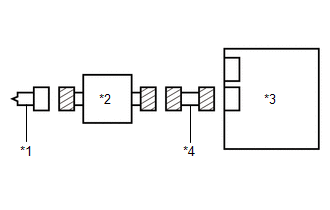
| (a) Disconnect the connectors from the horn button assembly, spiral cable sub-assembly and airbag sensor assembly. |
|
(b) Check that the terminals of the connectors are not deformed or damaged.
OK:
The terminals of the connectors are not deformed or damaged.
(c) Check that the short springs of the activation prevention mechanisms of the wire harness connector and spiral cable sub-assembly connector are not deformed or damaged.
OK:
The short springs are not deformed or damaged.
| NG |
 | REPLACE SPIRAL CABLE SUB-ASSEMBLY OR REPAIR OR REPLACE WIRE HARNESS |
|

| 4. | CHECK HORN BUTTON ASSEMBLY |
| (a) Connect the connectors to the airbag sensor assembly and spiral cable sub-assembly. |
|
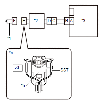
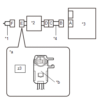
(b) Connect the white wire side of SST (resistance 2.1 Ω) to connector E (light green connector).
CAUTION:
Never connect a tester to the horn button assembly for measurement, as this may lead to a serious injury due to airbag deployment.
NOTICE:
- Do not forcibly insert SST into the terminals of the connector when connecting it.
- Insert SST straight into the terminals of the connector.
SST: 09843-18061
(c) Connect the cable to the negative (-) auxiliary battery terminal.
(d) Turn the ignition switch to ON, and wait for at least 60 seconds.
(e) Clear the DTCs stored in memory.
Body Electrical > SRS Airbag > Clear DTCs(f) Turn the ignition switch off.
|

| 5. | CHECK HORN BUTTON ASSEMBLY |
(a) Turn the ignition switch to ON, and wait for at least 60 seconds.
(b) Check for DTCs.
Body Electrical > SRS Airbag > Trouble CodesHINT:
Codes other than DTC B000111 may be output at this time, but they are not related to this check.
| Result | Proceed to |
|---|---|
| B000111 is not output | A |
| B000111 is output | B |
(c) Turn the ignition switch off.
(d) Disconnect the cable from the negative (-) auxiliary battery terminal.
CAUTION:
Wait at least 60 seconds after disconnecting the cable from the negative (-) auxiliary battery terminal to disable the SRS system.
(e) Disconnect SST from connector E.
| A |
 | REPLACE HORN BUTTON ASSEMBLY |
|

| 6. | CHECK DRIVER SEAT AIRBAG SQUIB CIRCUIT |
| (a) Disconnect the connector from the airbag sensor assembly. |
|
(b) Check for a short to ground in the circuit.
(1) Measure the resistance according to the value(s) in the table below.
Standard Resistance:
| Tester Connection | Condition | Specified Condition |
|---|---|---|
| z3-2 - Body ground | Always | 1 MΩ or higher |
| z3-1 - Body ground | Always | 1 MΩ or higher |
| NG |
 | GO TO STEP 9 |
|

| 7. | CLEAR DTC |
| (a) Connect the connectors to the horn button assembly and airbag sensor assembly. |
|
(b) Connect the cable to the negative (-) auxiliary battery terminal.
(c) Turn the ignition switch to ON, and wait for at least 60 seconds.
(d) Clear the DTCs stored in memory.
Body Electrical > SRS Airbag > Clear DTCs(e) Turn the ignition switch off.
|

| 8. | CHECK DTC |
(a) Turn the ignition switch to ON, and wait for at least 60 seconds.
(b) Check for DTCs.
Body Electrical > SRS Airbag > Trouble Codes| Result | Proceed to |
|---|---|
| B000111 is not output | A |
| B000111 is output | B |
HINT:
Codes other than DTC B000111 may be output at this time, but they are not related to this check.
| A |
 | USE SIMULATION METHOD TO CHECK |
| B |
 | REPLACE AIRBAG SENSOR ASSEMBLY |
| 9. | CHECK WIRE HARNESS |
| (a) Disconnect the connector from the spiral cable sub-assembly. |
|
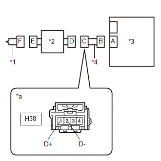
(b) Check for a short to ground in the circuit.
(1) Measure the resistance according to the value(s) in the table below.
Standard Resistance:
| Tester Connection | Condition | Specified Condition |
|---|---|---|
| H38-1 (D+) - Body ground | Always | 1 MΩ or higher |
| H38-2 (D-) - Body ground | Always | 1 MΩ or higher |
| OK |
 | REPLACE SPIRAL CABLE SUB-ASSEMBLY |
| NG |
 | REPAIR OR REPLACE HARNESS OR CONNECTOR |
 VEHICLE CONTROL HISTORY (RoB)
VEHICLE CONTROL HISTORY (RoB) NOTICE:
Replacing or repairing related components may cause vehicle control history codes to be stored.
When checking the vehicle control history, make sure to record the output histories...
 Driver Frontal Stage 1 Deployment Control Circuit Short to Battery (B000112)
DESCRIPTION DTC No. Detection Item DTC Detection Condition Trouble Area Warning Indicate Test Mode / Check Mode B000112 Driver Frontal Stage 1 Deployment Control Circuit Short to Battery
The airbag sensor assembly detects a short to B+ in the driver seat airbag squib circuit for 0...
Other information:
Toyota Yaris XP210 (2020-2025) Reapir and Service Manual: Engine Immobiliser System Circuit Short to Battery (B279A12)
DESCRIPTION If the communication line (IMI - EFIO) between the ECM and ID code box (immobiliser code ECU) is stuck high, the ECM will store this DTC. DTC No. Detection Item DTC Detection Condition Trouble Area Note B279A12 Engine Immobiliser System Circuit Short to Battery The communication line (IMI - EFIO) between the ECM and ID code box (immobiliser code ECU) is stuck high...
Toyota Yaris XP210 (2020-2025) Owner's Manual: Agreements and disclaimers related to Apple CarPlay™
This unit is compatible with Apple CarPlay™ which can operate an iPhone® using the vehicle’s audio device. iPhone, Siri and Apple Music are registered trademarks of Apple Inc. Apple CarPlay is trademarks of Apple Inc. iOS is a trademark or registered trademark of Cisco in the U...
Categories
- Manuals Home
- Toyota Yaris Owners Manual
- Toyota Yaris Service Manual
- Auto Lock/Unlock Function
- Engine Start Function When Key Battery is Dead
- Headlights
- New on site
- Most important about car
Key Suspend Function
If a key is left in the vehicle, the functions of the key left in the vehicle are temporarily suspended to prevent theft of the vehicle.
To restore the functions, press the unlock button on the functions-suspended key in the vehicle.