Toyota Yaris: Meter / Gauge System / Fuel Sender Circuit Open (B150013,B150113)
DESCRIPTION
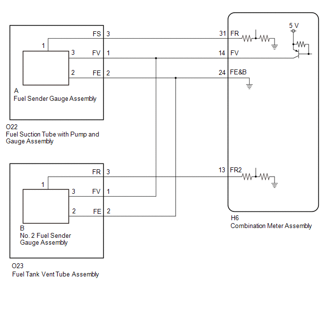
- The fuel sender gauge assembly is connected to the combination meter assembly via direct line. If there is an open or short in the direct line, the combination meter assembly stores DTC B150013.
- The fuel sender gauge assembly and No. 2 fuel sender gauge assembly are connected to the combination meter assembly via direct line. If there is an open or short in the direct line, the combination meter assembly stores DTC B150013 or B150113.
| DTC No. | Detection Item | DTC Detection Condition | Trouble Area |
|---|---|---|---|
| B150013 | Fuel Sender Circuit Open | Diagnosis Condition:
Malfunction Status:
Malfunction Time:
|
|
| B150113 | Sub Fuel Sender Circuit Open | Diagnosis Condition:
Malfunction Status:
Malfunction Time:
|
|
WIRING DIAGRAM
CAUTION / NOTICE / HINT
NOTICE:
When replacing the combination meter assembly, always replace it with a new one. If a combination meter assembly which was installed to another vehicle is used, the information stored in it will not match the information from the vehicle and a DTC may be stored.
PROCEDURE
| 1. | CHECK FOR DTC |
(a) Check for DTCs
Body Electrical > Combination Meter > Trouble Codes| Result | Proceed to |
|---|---|
| B150013 is output | A |
| B150113 is output | B |
| B150013 and B150113 are output | C |
| B |
 | GO TO STEP 6 |
| C |
 | GO TO STEP 10 |
|

| 2. | READ VALUE USING GTS |
(a) Read the Data List according to the display on the GTS.
Body Electrical > Combination Meter > Data List| Tester Display | Measurement Item | Range | Normal Condition | Diagnostic Note |
|---|---|---|---|---|
| Fuel Input | Fuel input | Min.: 0.00 L, Max.: 655.35 L or Unset | Fuel sender input value | - |
| Tester Display |
|---|
| Fuel Input |
| Result | Proceed to |
|---|---|
| Fuel level data can be displayed on the GTS. | A |
| Fuel level data cannot be displayed on the GTS | B |
| A |
 | REPLACE COMBINATION METER ASSEMBLY |
|

| 3. | CHECK HARNESS AND CONNECTOR (FUEL SUCTION TUBE WITH PUMP AND GAUGE ASSEMBLY - COMBINATION METER ASSEMBLY) |
Pre-procedure1
(a) Disconnect the O22 fuel suction tube with pump and gauge assembly connector.
(b) Disconnect the H6 combination meter assembly connector.
Procedure1
(c) Measure the resistance according to the value(s) in the table below.
Standard Resistance:
| Tester Connection | Condition | Specified Condition |
|---|---|---|
| O22-1 (FV) - H6-14 (FV) | Always | Below 1 Ω |
| O22-3 (FS) - H6-31 (FR) | Always | Below 1 Ω |
| O22-2 (FE) - H6-24 (FE&B) | Always | Below 1 Ω |
| O22-1 (FV) or H6-14 (FV) - Body ground | Always | 10 kΩ or higher |
| O22-3 (FS) or H6-31 (FR) - Body ground | Always | 10 kΩ or higher |
Post-procedure1
(d) None
| NG |
 | REPAIR OR REPLACE HARNESS OR CONNECTOR |
|

| 4. | INSPECT FUEL SENDER GAUGE ASSEMBLY |
Click here

| NG |
 | REPLACE FUEL SENDER GAUGE ASSEMBLY |
|

| 5. | INSPECT FUEL SUCTION TUBE WITH PUMP AND GAUGE ASSEMBLY |
(a) Measure the resistance according to the value(s) in the table below.

| *a | Component without harness connected (Fuel Suction Tube with Pump and Gauge Assembly) | - | - |
Standard Resistance:
| Tester Connection | Condition | Specified Condition |
|---|---|---|
| O22-1 (FV) - A-3 | Always | Below 1 Ω |
| O22-2 (FE) - A-2 | Always | Below 1 Ω |
| O22-3 (FS) - A-1 | Always | Below 1 Ω |
| O22-1 (FV) - O22-3 (FS) or A-3 - A-1 | Always | 10 kΩ or higher |
| O22-1 (FV) - O22-2 (FE) or A-3 - A-2 | Always | 10 kΩ or higher |
| O22-2 (FE) - O22-3 (FS) or A-2 - A-1 | Always | 10 kΩ or higher |
| OK |
 | REPLACE COMBINATION METER ASSEMBLY |
| NG |
 | REPLACE FUEL SUCTION TUBE WITH PUMP AND GAUGE ASSEMBLY |
| 6. | READ VALUE USING GTS |
(a) Read the Data List according to the display on the GTS.
Body Electrical > Combination Meter > Data List| Tester Display | Measurement Item | Range | Normal Condition | Diagnostic Note |
|---|---|---|---|---|
| Sub Fuel Input | Sub fuel input | Min.: 0.00 L, Max.: 655.35 L or Unset | Fuel sender input value | - |
| Tester Display |
|---|
| Sub Fuel Input |
| Result | Proceed to |
|---|---|
| Fuel level data can be displayed on the GTS. | A |
| Fuel level data cannot be displayed on the GTS | B |
| A |
 | REPLACE COMBINATION METER ASSEMBLY |
|

| 7. | CHECK HARNESS AND CONNECTOR (FUEL TANK VENT TUBE ASSEMBLY - COMBINATION METER ASSEMBLY) |
Pre-procedure1
(a) Disconnect the O23 fuel tank vent tube assembly connector.
(b) Disconnect the H6 combination meter assembly connector.
Procedure1
(c) Measure the resistance according to the value(s) in the table below.
Standard Resistance:
| Tester Connection | Condition | Specified Condition |
|---|---|---|
| O23-3 (FR) - H6-13 (FR2) | Always | Below 1 Ω |
| O23-1 (FV) - H6-14 (FV) | Always | Below 1 Ω |
| O23-2 (FE) - H6-24 (FE&B) | Always | Below 1 Ω |
| O23-3 (FR) or H6-13 (FR2)- Body ground | Always | 10 kΩ or higher |
Post-procedure1
(d) None
| NG |
 | REPAIR OR REPLACE HARNESS OR CONNECTOR |
|

| 8. | INSPECT NO. 2 FUEL SENDER GAUGE ASSEMBLY |
Click here

| NG |
 | REPLACE NO. 2 FUEL SENDER GAUGE ASSEMBLY |
|

| 9. | INSPECT FUEL TANK VENT TUBE ASSEMBLY |
(a) Measure the resistance according to the value(s) in the table below.

| *a | Component without harness connected (Fuel Tank Vent Tube Assembly) | - | - |
Standard Resistance:
| Tester Connection | Condition | Specified Condition |
|---|---|---|
| O23-1 (FV) - B-3 | Always | Below 1 Ω |
| O23-2 (FE) - B-2 | Always | Below 1 Ω |
| O23-3 (FR) - B-1 | Always | Below 1 Ω |
| O23-1 (FV) - O23-2 (FE) or B-3 - B-2 | Always | 10 kΩ or higher |
| O23-1 (FV) - O23-3 (FR) or B-3 - B-1 | Always | 10 kΩ or higher |
| O23-2 (FE) - O23-3 (FR) or B-2 - B-1 | Always | 10 kΩ or higher |
| OK |
 | REPLACE COMBINATION METER ASSEMBLY |
| NG |
 | REPLACE FUEL TANK VENT TUBE ASSEMBLY |
| 10. | READ VALUE USING GTS |
(a) Read the Data List according to the display on the GTS.
Body Electrical > Combination Meter > Data List| Tester Display | Measurement Item | Range | Normal Condition | Diagnostic Note |
|---|---|---|---|---|
| Fuel Input | Fuel input | Min.: 0.00 L, Max.: 655.35 L or Unset | Fuel sender input value | - |
| Sub Fuel Input | Sub fuel input | Min.: 0.00 L, Max.: 655.35 L or Unset | Fuel sender input value | - |
| Tester Display |
|---|
| Fuel Input |
| Sub Fuel Input |
| Result | Proceed to |
|---|---|
| Fuel level data can be displayed on the GTS. | A |
| Fuel level data cannot be displayed on the GTS | B |
| A |
 | REPLACE COMBINATION METER ASSEMBLY |
|

| 11. | CHECK HARNESS AND CONNECTOR (FUEL SUCTION TUBE WITH PUMP AND GAUGE ASSEMBLY AND FUEL TANK VENT TUBE ASSEMBLY - COMBINATION METER ASSEMBLY) |
Pre-procedure1
(a) Disconnect the O22 fuel suction tube with pump and gauge assembly connector.
(b) Disconnect the O23 fuel tank vent tube assembly connector.
(c) Disconnect the H6 combination meter assembly connector.
Procedure1
(d) Measure the resistance according to the value(s) in the table below.
Standard Resistance:
| Tester Connection | Condition | Specified Condition |
|---|---|---|
| O22-1 (FV) - H6-14 (FV) | Always | Below 1 Ω |
| O22-2 (FE) - H6-24 (FE&B) | Always | Below 1 Ω |
| O23-1 (FV) - H6-14 (FV) | Always | Below 1 Ω |
| O23-2 (FE) - H6-24 (FE&B) | Always | Below 1 Ω |
| O22-1 (FV), O23-1 (FV) or H6-14 (FV)- Body ground | Always | 10 kΩ or higher |
Post-procedure1
(e) None
| OK |
 | REPLACE COMBINATION METER ASSEMBLY |
| NG |
 | REPAIR OR REPLACE HARNESS OR CONNECTOR |
 On-vehicle Inspection
ON-VEHICLE INSPECTION PROCEDURE 1. INSPECT SPEEDOMETER NOTICE:
The combination meter assembly receives the vehicle speed signal from the skid control ECU (brake actuator assembly) via CAN communication...
 Turn Signal Light Circuit Current Below Threshold (B150718)
DESCRIPTION This DTC is stored when the combination meter assembly detects an open in a front turn signal light circuit or rear turn signal light circuit...
Other information:
Toyota Yaris XP210 (2020-2026) Owner's Manual: Removing a Flat Tire
If your vehicle is equipped with a wheel cover, pry off the wheel cover with the beveled end of the jack lever.Force the end of the jack lever firmly between wheel and cover, or removal will be difficult. Loosen the lug nuts by turning them counterclockwise one turn each, but do not remove any lug nuts until the tire has been raised off the ground...
Toyota Yaris XP210 (2020-2026) Reapir and Service Manual: Removal
REMOVAL PROCEDURE 1. REMOVE BACK DOOR TRIM BOARD Click here 2. REMOVE BACK DOOR TRIM COVER Click here 3. REMOVE BACK DOOR OUTSIDE GARNISH SUB-ASSEMBLY (a) Remove the 4 bolts. (b) Apply protective tape around the back door outside garnish sub-assembly...
Categories
- Manuals Home
- Toyota Yaris Owners Manual
- Toyota Yaris Service Manual
- Fuel Gauge
- Opening and Closing the Liftgate/Trunk Lid
- Brake System Control Module "A" System Voltage System Voltage Low (C137BA2)
- New on site
- Most important about car
Liftgate/Trunk Lid
WARNING
Never allow a person to ride in the luggage compartment/trunk
Allowing a person to ride in the luggage compartment/trunk is dangerous. The person in the luggage compartment/trunk could be seriously injured or killed during sudden braking or a collision.
Do not drive with the liftgate/trunk lid open