Toyota Yaris: Meter / Gauge System / Turn Signal Light Circuit Current Below Threshold (B150718)
DESCRIPTION
This DTC is stored when the combination meter assembly detects an open in a front turn signal light circuit or rear turn signal light circuit.
HINT:
- If there is an open in a front turn signal light circuit or rear turn signal light circuit, the turn signal lights on the side with the open circuit will blink faster than usual.
- If there is an open in a side turn signal light circuit, DTC B150718 will not be stored.
| DTC No. | Detection Item | DTC Detection Condition | Trouble Area |
|---|---|---|---|
| B150718 | Turn Signal Light Circuit Current Below Threshold | Diagnosis Condition:
Malfunction Status:
|
|
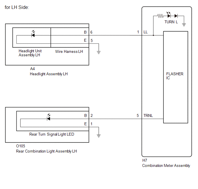
WIRING DIAGRAM

CAUTION / NOTICE / HINT
NOTICE:
- When replacing the combination meter assembly, always replace it with a new one. If a combination meter assembly which was installed to another vehicle is used, the information stored in it will not match the information from the vehicle and a DTC may be stored.
- Inspect the turn signal light bulbs before performing the following procedure.
PROCEDURE
| 1. | CHECK SYMPTOMS |
(a) Check the problem symptoms.
| Result | Proceed to |
|---|---|
| LH side front turn signal light does not blink | A |
| LH side rear turn signal light does not blink | B |
| RH side front turn signal light does not blink | C |
| RH side rear turn signal light does not blink | D |
| B |
 | GO TO STEP 5 |
| C |
 | GO TO STEP 7 |
| D |
 | GO TO STEP 10 |
|

| 2. | CHECK LH SIDE FRONT TURN SIGNAL LIGHT (HEADLIGHT ASSEMBLY LH) |
Pre-procedure1
(a) Interchange the headlight assembly LH with RH and connect the connectors.
HINT:
Click here

Procedure1
(b) Operate the turn signal switch and check that the LH side front turn signal light operates normally.
HINT:
If the RH side front turn signal light operates normally, the headlight assembly LH is malfunctioning.
Post-procedure1
(c) None
| Result | Proceed to |
|---|---|
| LH side front turn signal light operates normally | A |
| LH side front turn signal light does not blink | B |
| B |
 | GO TO STEP 4 |
|

| 3. | CHECK LH SIDE FRONT TURN SIGNAL LIGHT (WIRE HARNESS) |
(a) Interchange the wire harness LH with RH and connect the connectors.
HINT:
Click here

(b) Operate the turn signal switch and check that the LH side front turn signal light operates normally.
HINT:
If the LH side front turn signal light operates normally, the wire harness is malfunctioning.
| Result | Proceed to |
|---|---|
| LH side front turn signal light operates normally | A |
| LH side front turn signal light does not blink | B |
| A |
 | REPLACE WIRE HARNESS LH |
| B |
 | REPLACE HEADLIGHT UNIT ASSEMBLY LH |
| 4. | CHECK HARNESS AND CONNECTOR (HEADLIGHT ASSEMBLY LH - COMBINATION METER ASSEMBLY AND BODY GROUND) |
Pre-procedure1
(a) Disconnect the A4 headlight assembly LH connector.
(b) Disconnect the H7 combination meter assembly connector.
Procedure1
(c) Measure the resistance according to the value(s) in the table below.
Standard Resistance:
| Tester Connection | Condition | Specified Condition |
|---|---|---|
| A4-6 (B) - H7-1 (LL) | Always | Below 1 Ω |
| A4-5 (E) - Body ground | Always | Below 1 Ω |
Post-procedure1
(d) None
| OK |
 | REPLACE COMBINATION METER ASSEMBLY |
| NG |
 | REPAIR OR REPLACE HARNESS OR CONNECTOR |
| 5. | CHECK LH SIDE REAR TURN SIGNAL LIGHT (REAR TURN SIGNAL LIGHT LED) |
Pre-procedure1
(a) Interchange the rear turn signal light LED LH with RH and connect the connectors.
HINT:
Click here

Procedure1
(b) Operate the turn signal switch and check that the LH side rear turn signal light operates normally.
HINT:
If the LH side rear turn signal lights operates normally, the rear turn signal light LED is malfunctioning.
Post-procedure1
(c) None
| Result | Proceed to |
|---|---|
| LH side rear turn signal lights operates normally | A |
| LH side rear turn signal light does not blink | B |
| A |
 | REPLACE REAR TURN SIGNAL LIGHT LED |
|

| 6. | CHECK HARNESS AND CONNECTOR (REAR COMBINATION LIGHT ASSEMBLY LH - COMBINATION METER ASSEMBLY AND BODY GROUND) |
Pre-procedure1
(a) Disconnect the O105 rear combination light assembly LH connector.
(b) Disconnect the H7 combination meter assembly connector.
Procedure1
(c) Measure the resistance according to the value(s) in the table below.
Standard Resistance:
| Tester Connection | Condition | Specified Condition |
|---|---|---|
| O105-2 (B) - H7-5 (TRNL) | Always | Below 1 Ω |
| O105-1 (E) - Body ground | Always | Below 1 Ω |
Pre-procedure1
(d) None
| OK |
 | REPLACE COMBINATION METER ASSEMBLY |
| NG |
 | REPAIR OR REPLACE HARNESS OR CONNECTOR |
| 7. | CHECK RH SIDE FRONT TURN SIGNAL LIGHT (HEADLIGHT ASSEMBLY RH) |
Pre-procedure1
(a) Interchange the headlight assembly RH with LH and connect the connectors.
HINT:
Click here

Procedure1
(b) Operate the turn signal switch and check that the RH side front turn signal light operates normally.
HINT:
If the RH side front turn signal light operates normally, the headlight assembly RH is malfunctioning.
Post-procedure1
(c) None
| Result | Proceed to |
|---|---|
| RH side front turn signal light operates normally | A |
| RH side front turn signal light does not blink | B |
| B |
 | GO TO STEP 9 |
|

| 8. | CHECK RH SIDE FRONT TURN SIGNAL LIGHT (WIRE HARNESS) |
Pre-procedure1
(a) Interchange the wire harness RH with LH and connect the connectors.
HINT:
Click here

Procedure1
(b) Operate the turn signal switch and check that the RH side front turn signal light operates normally.
HINT:
If the RH side front turn signal light operates normally, the wire harness RH is malfunctioning.
Post-procedure1
(c) None
| Result | Proceed to |
|---|---|
| RH side front turn signal light operates normally | A |
| RH side front turn signal light does not blink | B |
| A |
 | REPLACE WIRE HARNESS RH |
| B |
 | REPLACE HEADLIGHT UNIT ASSEMBLY RH |
| 9. | CHECK HARNESS AND CONNECTOR (HEADLIGHT ASSEMBLY RH - COMBINATION METER ASSEMBLY AND BODY GROUND) |
Pre-procedure1
(a) Disconnect the A5 headlight assembly RH connector.
(b) Disconnect the H7 combination meter assembly connector.
Procedure1
(c) Measure the resistance according to the value(s) in the table below.
Standard Resistance:
| Tester Connection | Condition | Specified Condition |
|---|---|---|
| A5-6 (B) - H7-2 (LR) | Always | Below 1 Ω |
| A5-5 (E) - Body ground | Always | Below 1 Ω |
Post-procedure1
(d) None
| OK |
 | REPLACE COMBINATION METER ASSEMBLY |
| NG |
 | REPAIR OR REPLACE HARNESS OR CONNECTOR |
| 10. | CHECK RH SIDE REAR TURN SIGNAL LIGHT (REAR TURN SIGNAL LIGHT LED) |
Pre-procedure1
(a) Interchange the rear turn signal light LED RH with LH and connect the connectors.
HINT:
Click here

Procedure1
(b) Operate the turn signal switch and check that the RH side rear turn signal light operates normally.
HINT:
If the RH side rear turn signal lights operates normally, the rear turn signal light LED is malfunctioning.
Post-procedure1
(c) None
| Result | Proceed to |
|---|---|
| RH side rear turn signal lights operates normally | A |
| RH side rear turn signal light does not blink | B |
| A |
 | REPLACE REAR TURN SIGNAL LIGHT LED |
|

| 11. | CHECK HARNESS AND CONNECTOR (REAR COMBINATION LIGHT ASSEMBLY RH - COMBINATION METER ASSEMBLY AND BODY GROUND) |
Pre-procedure1
(a) Disconnect the O106 rear combination light assembly RH connector.
(b) Disconnect the H7 combination meter assembly connector.
Procedure1
(c) Measure the resistance according to the value(s) in the table below.
Standard Resistance:
| Tester Connection | Condition | Specified Condition |
|---|---|---|
| O106-2 (B) - H7-6 (TRNR) | Always | Below 1 Ω |
| O106-1 (E) - Body ground | Always | Below 1 Ω |
Post-procedure1
(d) None
| OK |
 | REPLACE COMBINATION METER ASSEMBLY |
| NG |
 | REPAIR OR REPLACE HARNESS OR CONNECTOR |
 Fuel Sender Circuit Open (B150013,B150113)
DESCRIPTION
The fuel sender gauge assembly is connected to the combination meter assembly via direct line. If there is an open or short in the direct line, the combination meter assembly stores DTC B150013...
 Turn Signal/Hazard Flasher Circuit Current Above Threshold (B150819)
DESCRIPTION This DTC is stored when the combination meter assembly detects a short in a turn signal light circuit. HINT: If there is a short in a turn signal light circuit, all of the turn signal lights in that circuit will not blink...
Other information:
Toyota Yaris XP210 (2020-2026) Owner's Manual: Dehumidifying
Operate the air conditioner in cool or cold weather to help defog the windshield and side windows. Set the mode selector dial to the desired position. Set the air intake selector to the outside air position. Set the temperature control dial to the desired position...
Toyota Yaris XP210 (2020-2026) Reapir and Service Manual: Back Door Entry Lock Function does not Operate
DESCRIPTION If the entry lock function does not operate for the back door only, but the entry unlock function operates, the request code is being transmitted properly from the back door. In this case, there may be a problem related to the lock switch (connection between the back door opener switch assembly and certification ECU (smart key ECU assembly))...
Categories
- Manuals Home
- Toyota Yaris Owners Manual
- Toyota Yaris Service Manual
- Diagnostic Trouble Code Chart
- Engine Start Function When Key Battery is Dead
- How to use USB mode
- New on site
- Most important about car
Refueling
Before refueling, close all the doors, windows, and the liftgate/trunk lid, and switch the ignition OFF.
To open the fuel-filler lid, pull the remote fuel-filler lid release.
