Toyota Yaris: Meter / Gauge System / Turn Signal/Hazard Flasher Circuit Current Above Threshold (B150819)
DESCRIPTION
This DTC is stored when the combination meter assembly detects a short in a turn signal light circuit.
HINT:
If there is a short in a turn signal light circuit, all of the turn signal lights in that circuit will not blink.
| DTC No. | Detection Item | DTC Detection Condition | Trouble Area |
|---|---|---|---|
| B150819 | Turn Signal/Hazard Flasher Circuit Current Above Threshold | Diagnosis Condition:
Malfunction Status:
|
|
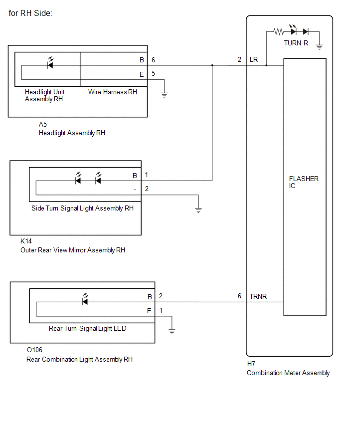
WIRING DIAGRAM

CAUTION / NOTICE / HINT
NOTICE:
- When replacing the combination meter assembly, always replace it with a new one. If a combination meter assembly which was installed to another vehicle is used, the information stored in it will not match the information from the vehicle and a DTC may be stored.
- Inspect the turn signal light bulbs before performing the following procedure.
PROCEDURE
| 1. | CHECK SYMPTOMS |
(a) Check the problem symptoms.
| Result | Proceed to |
|---|---|
| All LH side turn signal lights do not blink | A |
| All RH side turn signal lights do not blink | B |
| B |
 | GO TO STEP 8 |
|

| 2. | CHECK LH SIDE TURN SIGNAL LIGHTS (FRONT TURN SIGNAL LIGHT CIRCUIT) |
Pre-procedure1
(a) Disconnect the A4 headlight assembly LH connector.
Procedure1
(b) Operate the turn signal switch and check that the LH side turn signal lights other than the front turn signal light blink.
HINT:
If the LH side turn signal lights other than the front turn signal light blink, the headlight assembly LH is malfunctioning.
Post-procedure1
(c) None
| Result | Proceed to |
|---|---|
| LH side turn signal lights other than the front turn signal light blink | A |
| All LH side turn signal lights do not blink | B |
| B |
 | GO TO STEP 4 |
|

| 3. | CHECK LH SIDE TURN SIGNAL LIGHTS (WIRE HARNESS) |
(a) Remove the headlight unit assembly LH from headlight assembly LH.
HINT:
Click here

(b) Connect the headlight assembly LH connector.
(c) Operate the turn signal switch and check that the LH side turn signal lights other than the front turn signal light blink.
HINT:
If all LH side turn signal lights do not blink, the wire harness LH is malfunctioning.
| Result | Proceed to |
|---|---|
| LH side turn signal lights other than the front turn signal light blink | A |
| All LH side turn signal lights do not blink | B |
| A |
 | REPLACE HEADLIGHT UNIT ASSEMBLY LH |
| B |
 | REPLACE WIRE HARNESS LH |
| 4. | CHECK LH SIDE TURN SIGNAL LIGHTS (SIDE TURN SIGNAL LIGHT CIRCUIT) |
Pre-procedure1
(a) Connect the headlight assembly LH connector.
(b) Disconnect the L14 outer rear view mirror assembly LH connector.
Procedure1
(c) Operate the turn signal switch and check that the LH side turn signal lights other than the side turn signal light blink.
HINT:
If the LH side turn signal lights other than the side turn signal light blink, a component of the outer rear view mirror assembly LH is malfunctioning.
Post-procedure1
(d) None
| Result | Proceed to |
|---|---|
| LH side turn signal lights other than the side turn signal light blink | A |
| All LH side turn signal lights do not blink | B |
| B |
 | GO TO STEP 6 |
|

| 5. | CHECK LH SIDE TURN SIGNAL LIGHTS (OUTER REAR VIEW MIRROR ASSEMBLY LH) |
Pre-procedure1
(a) Remove the side turn signal light assembly LH from outer rear view mirror assembly LH.
Click here

(b) Connect the outer rear view mirror assembly LH connector.
Procedure1
(c) Operate the turn signal switch and check that the LH side turn signal lights other than the side turn signal light blink.
HINT:
If all LH side turn signal lights do not blink, the outer rear view mirror assembly LH is malfunctioning.
Post-procedure1
(d) None
| Result | Proceed to |
|---|---|
| LH side turn signal lights other than the side turn signal light blink | A |
| All LH side turn signal lights do not blink | B |
| A |
 | REPLACE SIDE TURN SIGNAL LIGHT ASSEMBLY LH |
| B |
 | REPLACE OUTER REAR VIEW MIRROR ASSEMBLY LH |
| 6. | CHECK LH SIDE TURN SIGNAL LIGHTS (REAR TURN SIGNAL LIGHT CIRCUIT) |
Pre-procedure1
(a) Connect the outer rear view mirror assembly LH connector.
(b) Disconnect the O105 rear combination light assembly LH connector.
Procedure1
(c) Operate the turn signal switch and check that the LH side turn signal lights other than the rear turn signal light blink.
HINT:
If the LH side turn signal lights other than the rear turn signal light blink, the rear combination light assembly LH is malfunctioning.
Post-procedure1
(d) None
| Result | Proceed to |
|---|---|
| LH side turn signal lights other than the rear turn signal light blink | A |
| All LH side turn signal lights do not blink | B |
| A |
 | REPLACE REAR TURN SIGNAL LIGHT LED |
|

| 7. | CHECK HARNESS AND CONNECTOR (LH SIDE EACH PARTS - COMBINATION METER ASSEMBLY) |
Pre-procedure1
(a) Disconnect the A4 headlight assembly LH connector.
(b) Disconnect the L14 outer rear view mirror assembly LH connector.
(c) Disconnect the H7 combination meter assembly connector.
Procedure1
(d) Measure the resistance according to the value(s) in the table below.
Standard Resistance:
| Tester Connection | Condition | Specified Condition |
|---|---|---|
| A4-6 (B) - Body ground | Always | 10 kΩ or higher |
| L14-1 (B) - Body ground | Always | 10 kΩ or higher |
| O105-2 (B) - Body ground | Always | 10 kΩ or higher |
| H7-1 (LL) - Body ground | Always | 10 kΩ or higher |
| H7-5 (TRNL) - Body ground | Always | 10 kΩ or higher |
Post-procedure1
(e) None
| OK |
 | REPLACE COMBINATION METER ASSEMBLY |
| NG |
 | REPAIR OR REPLACE HARNESS OR CONNECTOR |
| 8. | CHECK RH SIDE TURN SIGNAL LIGHTS (FRONT TURN SIGNAL LIGHT CIRCUIT) |
Pre-procedure1
(a) Disconnect the A5 headlight assembly RH connector.
Procedure1
(b) Operate the turn signal switch and check that the RH side turn signal lights other than the front turn signal light blink.
HINT:
If the RH side turn signal lights other than the front turn signal light blink, the headlight assembly RH is malfunctioning.
Post-procedure1
(c) None
| Result | Proceed to |
|---|---|
| LH side turn signal lights other than the front turn signal light blink | A |
| All LH side turn signal lights do not blink | B |
| B |
 | GO TO STEP 10 |
|

| 9. | CHECK RH SIDE TURN SIGNAL LIGHTS (WIRE HARNESS) |
(a) Remove the headlight unit assembly RH from headlight assembly RH.
HINT:
Click here

(b) Connect the A5 headlight assembly RH connector.
(c) Operate the turn signal switch and check that the LH side turn signal lights other than the front turn signal light blink.
HINT:
If all LH side turn signal lights do not blink, the wire harness RH is malfunctioning.
| Result | Proceed to |
|---|---|
| LH side turn signal lights other than the front turn signal light blink | A |
| All LH side turn signal lights do not blink | B |
| A |
 | REPLACE HEADLIGHT UNIT ASSEMBLY RH |
| B |
 | REPLACE WIRE HARNESS RH |
| 10. | CHECK RH SIDE TURN SIGNAL LIGHTS (SIDE TURN SIGNAL LIGHT CIRCUIT) |
Pre-procedure1
(a) Connect the headlight assembly RH connector.
(b) Disconnect the K14 outer rear view mirror assembly RH connector.
Procedure1
(c) Operate the turn signal switch and check that the RH side turn signal lights other than the side turn signal light blink.
HINT:
If the RH side turn signal lights other than the side turn signal light blink, a component of the outer rear view mirror assembly RH is malfunctioning.
Post-procedure1
(d) None
| Result | Proceed to |
|---|---|
| RH side turn signal lights other than the side turn signal light blink | A |
| All RH side turn signal lights do not blink | B |
| B |
 | GO TO STEP 12 |
|

| 11. | CHECK RH SIDE TURN SIGNAL LIGHTS (OUTER REAR VIEW MIRROR ASSEMBLY RH) |
Pre-procedure1
(a) Remove the side turn signal light assembly RH from outer rear view mirror assembly RH.
Click here

(b) Connect the K14 outer rear view mirror assembly RH connector.
Procedure1
(c) Operate the turn signal switch and check that the RH side turn signal lights other than the side turn signal light blink.
HINT:
If all RH side turn signal lights do not blink, the outer rear view mirror assembly RH is malfunctioning.
Post-procedure1
(d) None
| Result | Proceed to |
|---|---|
| RH side turn signal lights other than the side turn signal light blink | A |
| All RH side turn signal lights do not blink | B |
| A |
 | REPLACE SIDE TURN SIGNAL LIGHT ASSEMBLY RH |
| B |
 | REPLACE OUTER REAR VIEW MIRROR ASSEMBLY RH |
| 12. | CHECK RH SIDE TURN SIGNAL LIGHTS (REAR TURN SIGNAL LIGHT CIRCUIT) |
Pre-procedure1
(a) Connect the outer rear view mirror assembly RH connector.
(b) Disconnect the O106 rear combination light assembly RH connector.
Procedure1
(c) Operate the turn signal switch and check that the RH side turn signal lights other than the rear turn signal light blink.
HINT:
If the RH side turn signal lights other than the rear turn signal light blink, the rear combination light cord RH is malfunctioning.
Post-procedure1
(d) None
| Result | Proceed to |
|---|---|
| RH side turn signal lights other than the rear turn signal light blink | A |
| All RH side turn signal lights do not blink | B |
| A |
 | REPLACE REAR TURN SIGNAL LIGHT LED |
|

| 13. | CHECK HARNESS AND CONNECTOR (RH SIDE EACH PARTS - COMBINATION METER ASSEMBLY) |
Pre-procedure1
(a) Disconnect the A5 headlight assembly RH connector.
(b) Disconnect the K14 outer rear view mirror assembly RH connector.
(c) Disconnect the H7 combination meter assembly connector.
Procedure1
(d) Measure the resistance according to the value(s) in the table below.
Standard Resistance:
| Tester Connection | Condition | Specified Condition |
|---|---|---|
| A5-6 (B) - Body ground | Always | 10 kΩ or higher |
| K14-1 (B) - Body ground | Always | 10 kΩ or higher |
| O106-2 (B) - Body ground | Always | 10 kΩ or higher |
| H7-2 (LR) - Body ground | Always | 10 kΩ or higher |
| H7-6 (TRNR) - Body ground | Always | 10 kΩ or higher |
Post-procedure1
(e) None
| OK |
 | REPLACE COMBINATION METER ASSEMBLY |
| NG |
 | REPAIR OR REPLACE HARNESS OR CONNECTOR |
 Turn Signal Light Circuit Current Below Threshold (B150718)
DESCRIPTION This DTC is stored when the combination meter assembly detects an open in a front turn signal light circuit or rear turn signal light circuit...
 Lost Communication With ECM/PCM "A" Missing Message (U010087,U011487,U012987,U013187,U014087,U015187,U016887,U023587,U023A87,U111287,U113387)
DESCRIPTION The combination meter assembly communicates with each ECU via CAN communication. DTC No. Detection Item DTC Detection Condition Trouble Area U010087 Lost Communication With ECM/PCM "A" Missing Message Diagnosis Condition:
The ignition switch is ON
IG power source voltage is 9...
Other information:
Toyota Yaris XP210 (2020-2026) Reapir and Service Manual: Fuel Rail / System Pressure - Too High (P008800)
DESCRIPTION Refer to DTC P008700. Click here DTC No. Detection Item DTC Detection Condition Trouble Area MIL Note P008800 Fuel Rail / System Pressure - Too High Although the ECM is requesting the fuel pump assembly (for high pressure side) to open the spill control valve, fuel pressure increases 3 MPa (30...
Toyota Yaris XP210 (2020-2026) Reapir and Service Manual: Road Test
ROAD TEST HINT: The dynamic radar cruise control system has 2 cruise control modes: constant speed control mode and vehicle-to-vehicle distance control mode. Vehicle-to-vehicle distance control mode is selected by default when the dynamic radar cruise control system is turned on using the cruise control main switch...
Categories
- Manuals Home
- Toyota Yaris Owners Manual
- Toyota Yaris Service Manual
- How to connect USB port/Auxiliary jack
- Immobilizer System
- Auto Lock/Unlock Function
- New on site
- Most important about car
Key Suspend Function
If a key is left in the vehicle, the functions of the key left in the vehicle are temporarily suspended to prevent theft of the vehicle.
To restore the functions, press the unlock button on the functions-suspended key in the vehicle.