Toyota Yaris: G16e-gts (engine Control) / Vacuum Sensor
Components
COMPONENTS
ILLUSTRATION
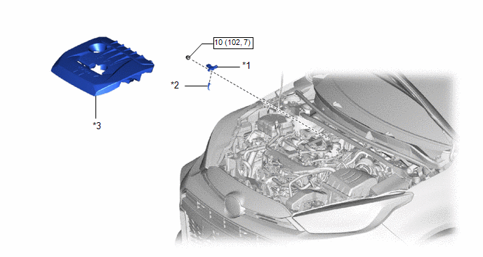
| *1 | E.F.I. VACUUM SENSOR ASSEMBLY | *2 | VACUUM HOSE |
| *3 | NO. 1 ENGINE COVER SUB-ASSEMBLY | - | - |
 | N*m (kgf*cm, ft.*lbf): Specified torque | - | - |
On-vehicle Inspection
ON-VEHICLE INSPECTION
PROCEDURE
1. INSPECT E.F.I. VACUUM SENSOR ASSEMBLY
(a) Connect the GTS to the DLC3.
(b) Start the engine.
(c) Turn the GTS on.
(d) Warm up the engine.
(e) Turn the A/C switch off.
(f) Enter the following menus: Powertrain / Engine / Data List / Turbocharger/Supercharger Inlet Pressure Bank1
Powertrain > Engine > Data List| Tester Display |
|---|
| Turbocharger/Supercharger Inlet Pressure Bank1 |
(g) Read the air pressure value from the Data List.
HINT:
- Standard atmospheric pressure is approximately 101 kPa (abs) (15 psi (abs)).
- For every 100 m (328 ft) increase in altitude, atmospheric pressure drops by approximately 1 kPa (0.15 psi). This varies by weather.
(h) Using a vacuum pump, set the E.F.I. vacuum sensor assembly.
(i) Using a vacuum pump, read the value when pressure is applied and when pressure is decreased.
OK:
The pressure values when applying pressure or decreasing pressure using the vacuum pump and the Data List values are nearly the same.
NOTICE:
- Do not apply a pressure of 50 kPa (0.5 kgf/cm2, 7.3 psi) or more to the E.F.I. vacuum sensor assembly (manifold absolute pressure sensor).
- Do not apply a vacuum of 50 kPa (375 mmHg, 14.8 in.Hg) or more to the E.F.I. vacuum sensor assembly (manifold absolute pressure sensor).
HINT:
The pressure value displayed in the Data List is the pressure value indicated on the vacuum pump with the air pressure value added.
Example:| Vacuum Pump Pressure Value | Air Pressure Value | Equation | Data List Value |
|---|---|---|---|
| When vacuum is applied at 30 kPa (225 mmHg, 8.86 in.Hg) | 100 kPa (1.0 kgf/cm2, 15 psi) | -30 + 100 = 70 | 70 kPa (0.7 kgf/cm2, 10.2 psi) |
| When pressure is applied at 20 kPa (0.2 kgf/cm2, 3 psi) | 20 + 100 = 120 | 120 kPa (1.2 kgf/cm2, 17 psi) |
Removal
REMOVAL
PROCEDURE
1. REMOVE NO. 1 ENGINE COVER SUB-ASSEMBLY
Click here

2. REMOVE E.F.I. VACUUM SENSOR ASSEMBLY
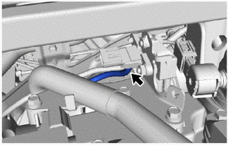
| (a) Disconnect the vacuum hose from the E.F.I. vacuum sensor assembly. |
|
| (b) Disconnect the E.F.I. vacuum sensor assembly connector. |
|
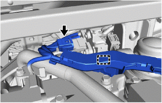
(c) Disengage the wire harness clamp.
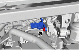
| (d) Remove the nut and E.F.I. vacuum sensor assembly from the intake pipe or hose stay. |
|
Installation
INSTALLATION
PROCEDURE
1. INSTALL E.F.I. VACUUM SENSOR ASSEMBLY
(a) Install the E.F.I. vacuum sensor assembly to the intake pipe or hose stay with the nut.
Torque:
10 N·m {102 kgf·cm, 7 ft·lbf}
(b) Connect the E.F.I. vacuum sensor assembly connector.
(c) Engage the wire harness clamp.
(d) Connect the vacuum hose to the E.F.I. vacuum sensor assembly.
2. INSTALL NO. 1 ENGINE COVER SUB-ASSEMBLY
Click here

 Throttle Body
ComponentsCOMPONENTS ILLUSTRATION
*1 AIR TUBE ASSEMBLY *2 THROTTLE BODY WITH MOTOR ASSEMBLY *3 THROTTLE BODY GASKET *4 NO. 2 THROTTLE BODY GASKET
N*m (kgf*cm, ft...

Other information:
Toyota Yaris XP210 (2020-2026) Reapir and Service Manual: Inspection
INSPECTION PROCEDURE 1. INSPECT REAR STABILIZER LINK ASSEMBLY (a) Inspect the turning torque of the ball joint. (1) Secure the rear stabilizer link assembly in a vise using aluminum plates. NOTICE: Do not overtighten the vise. (2) Install the nut to the rear stabilizer link assembly stud...
Toyota Yaris XP210 (2020-2026) Reapir and Service Manual: 4WD/AWD Front/Rear Range Actuator Control Circuit Performance Circuit Voltage Out of Range (C05F51C)
DESCRIPTION When a malfunction has occurred in the AWD coupling solenoid system, the AWD ECU assembly stores DTC C05F51C. DTC No. Detection Item DTC Detection Condition Trouble Area Warning Indicate Memory C05F51C 4WD/AWD Front/Rear Range Actuator Control Circuit Performance Circuit Voltage Out of Range When the IG1 terminal voltage is 9...
Categories
- Manuals Home
- Toyota Yaris Owners Manual
- Toyota Yaris Service Manual
- Diagnostic Trouble Code Chart
- Auto Lock/Unlock Function
- Key Battery Replacement
- New on site
- Most important about car
Break-In Period
No special break-in is necessary, but a few precautions in the first 600 miles (1,000 km) may add to the performance, economy, and life of the vehicle.
Do not race the engine. Do not maintain one constant speed, either slow or fast, for a long period of time. Do not drive constantly at full-throttle or high engine rpm for extended periods of time. Avoid unnecessary hard stops. Avoid full-throttle starts.