Toyota Yaris: G16e-gts (engine Control) / Throttle Body
Components
COMPONENTS
ILLUSTRATION
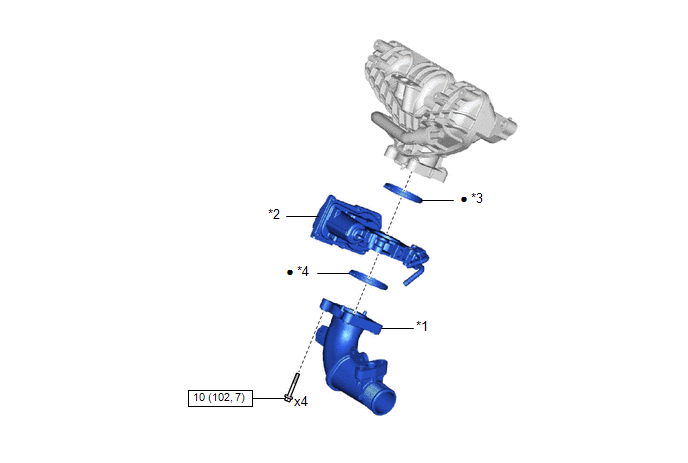
| *1 | AIR TUBE ASSEMBLY | *2 | THROTTLE BODY WITH MOTOR ASSEMBLY |
| *3 | THROTTLE BODY GASKET | *4 | NO. 2 THROTTLE BODY GASKET |
 | N*m (kgf*cm, ft.*lbf): Specified torque | ● | Non-reusable part |
On-vehicle Inspection
ON-VEHICLE INSPECTION
PROCEDURE
1. INSPECT THROTTLE BODY WITH MOTOR ASSEMBLY
(a) Check the idle speed.
(1) Start the engine and check that the MIL is not illuminated. After the engine is warmed up, check that the idle speed is within the specified range with the A/C switch off.
Standard Idle Speed:
950 to 1050 rpm
NOTICE:
- Be sure to perform this step with all accessories off.
- Make sure that the shift lever is in P or N.
(2) Perform a road test and confirm that there are no abnormalities.
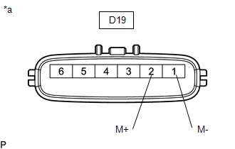
(b) Inspect the throttle position sensor.
(1) Connect the GTS to the DLC3.
(2) Start the engine.
(3) Turn the GTS on.
(4) Enter the following menus: Powertrain / Engine / Data List / Throttle Position Sensor No.1 Voltage %.
Powertrain > Engine > Data List| Tester Display |
|---|
| Throttle Position Sensor No.1 Voltage % |
(5) According to the display on the GTS, read the Data List while fully depressing the accelerator pedal and check that the value is 60% or higher.
If the value is less than 60%, check the throttle body with motor assembly, wire harness and ECM.
Removal
REMOVAL
CAUTION / NOTICE / HINT
The necessary procedures (adjustment, calibration, initialization or registration) that must be performed after parts are removed and installed, or replaced during throttle body with motor assembly removal/installation are shown below.
Necessary Procedure After Parts Removed/Installed/Replaced| Replacement Part or Procedure | Necessary Procedures | Effects/Inoperative when not performed | Link |
|---|---|---|---|
| Inspection after repair |
|
|

PROCEDURE
1. REMOVE INTAKE MANIFOLD ASSEMBLY
Click here

2. REMOVE AIR TUBE ASSEMBLY
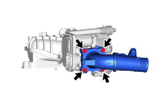
| (a) Remove the 4 bolts and air tube assembly from the throttle body with motor assembly. NOTICE: If the throttle body with motor assembly has been struck or dropped, replace it. |
|
(b) Remove the No. 2 throttle body gasket from the air tube assembly.
3. REMOVE THROTTLE BODY WITH MOTOR ASSEMBLY
| (a) Remove the throttle body with motor assembly from the intake manifold. NOTICE: If the throttle body with motor assembly has been struck or dropped, replace it. |
|
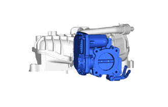
(b) Remove the throttle body gasket from the intake manifold.
Inspection
INSPECTION
PROCEDURE
1. INSPECT THROTTLE BODY WITH MOTOR ASSEMBLY
| (a) Measure the resistance according to the value(s) in the table below. Standard Resistance:
If the result is not as specified, replace the throttle body with motor assembly. |
|
Installation
INSTALLATION
PROCEDURE
1. INSTALL THROTTLE BODY WITH MOTOR ASSEMBLY
(a) Install a new throttle body gasket to the intake manifold.
(b) Install the throttle body with motor assembly to the intake manifold.
NOTICE:
If the throttle body with motor assembly has been struck or dropped, replace it.
2. INSTALL AIR TUBE ASSEMBLY
(a) Install the No. 2 throttle body gasket to the air tube assembly.
(b) Install the air tube assembly to the throttle body with motor assembly with the 4 bolts.
Torque:
10 N·m {102 kgf·cm}
3. INSTALL INTAKE MANIFOLD ASSEMBLY
Click here

4. INSPECT FUNCTION OF THROTTLE BODY WITH MOTOR ASSEMBLY
Click here

 Lack of Power (Turbocharger System)
CAUTION / NOTICE / HINT HINT:
The diagnosis flowchart is for lack of power due to turbocharger factors.
If symptom-specific diagnosis indicates a turbocharger related problem, check using this flowchart...
 Vacuum Sensor
ComponentsCOMPONENTS ILLUSTRATION
*1 E.F.I. VACUUM SENSOR ASSEMBLY *2 VACUUM HOSE *3 NO. 1 ENGINE COVER SUB-ASSEMBLY - -
N*m (kgf*cm, ft...
Other information:
Toyota Yaris XP210 (2020-2026) Reapir and Service Manual: Components
COMPONENTS ILLUSTRATION *1 REAR SPEED SENSOR *2 NO. 3 PARKING BRAKE CABLE ASSEMBLY Tightening torque for "Major areas involving basic vehicle performance such as moving/turning/stopping" : N*m (kgf*cm, ft.*lbf) N*m (kgf*cm, ft...
Toyota Yaris XP210 (2020-2026) Reapir and Service Manual: System Diagram
SYSTEM DIAGRAM (a) The CAN communication system is composed of 8 buses. CAN Main Bus Line Terminating Resistor CAN Branch Line * Gateway Function Equipped ECU Bus Monitoring Direction - - Connected to Code ECU/Sensor Name GTS Display Applicability - CGW Central Gateway ECU (Network Gateway ECU) - Installed on all vehicles - DLC3 DLC3 - Installed on all vehicles Bus 1 F-CAM Forward Recognition Camera Front Camera Module w/ Toyota Safety Sense F-MR Millimeter Wave Radar Sensor Assembly Front Radar w/ Toyota Safety Sense CAN Global J/C NO...
Categories
- Manuals Home
- Toyota Yaris Owners Manual
- Toyota Yaris Service Manual
- Removal
- Immobilizer System
- Brake System Control Module "A" System Voltage System Voltage Low (C137BA2)
- New on site
- Most important about car
Fuel Gauge
The fuel gauge shows approximately how much fuel is remaining in the tank when the ignition is switched ON. We recommend keeping the tank over 1/4 full.
