Toyota Yaris: Sfi System / Lack of Power (Turbocharger System)
CAUTION / NOTICE / HINT
HINT:
- The diagnosis flowchart is for lack of power due to turbocharger factors.
- If symptom-specific diagnosis indicates a turbocharger related problem, check using this flowchart.
PROCEDURE
| 1. | CHECK TURBOCHARGER SUB-ASSEMBLY |
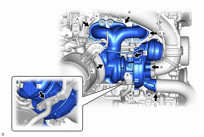
(a) Check for oil leaks and large carbon deposits around the connecting surfaces of the turbocharger sub-assembly.
HINT:
If oil leaks or a large amount of carbon deposits exist, air leaks from the respective sealing surfaces may be causing the lack of boost pressure.
| Result | Proceed to |
|---|---|
| An oil leak or large amount of carbon deposits does not exist. | A |
| A large amount of carbon deposits exist around the turbine housing, flange or gaskets in any of the areas (A) shown in the illustration. | B |
| A large amount of carbon deposits exist around the waste gate valve link. | C |
| Oil is leaking from between the sealing surfaces of the seal plate and compressor housing or bearing housing in the area (B) shown in the illustration. | D |
| Oil is leaking from the compressor housing in any of the areas (C) shown in the illustration. | E |
| B |
 | GO TO STEP 6 |
| C |
 | GO TO STEP 9 |
| D |
 | REPLACE TURBOCHARGER SUB-ASSEMBLY |
| E |
 | CHECK AND REPAIR AIR TUBE OR HOSE CLAMP |
|

| 2. | CHECK TURBOCHARGER SUB-ASSEMBLY (INSPECT TURBINE SHAFT) |
(a) Check for loose turbine mounting nuts and for axial play in the turbine shaft.
Click here

HINT:
If the turbine shaft catches or there is no play, seal failure due to seizure or improper operation due to accumulation of deposits is suspected.
| Result | Proceed to |
|---|---|
| No turbine shaft malfunction | A |
| Turbine shaft malfunction | B |
| B |
 | REPLACE TURBOCHARGER SUB-ASSEMBLY (TURBINE SHAFT MALFUNCTION) |
|

| 3. | CHECK TURBOCHARGER SUB-ASSEMBLY (INSPECT WASTE GATE VALVE) |
(a) Use a vacuum pump to apply -35 +/-4.0 kPa (-263 +/-35 mmHg) negative pressure to the diaphragm chamber and check that the waste gate valve seats.
NOTICE:
Do not apply a negative pressure of -65 kPa (-488 mmHg) or more to the waste gate valve actuator with bracket assembly, as doing so may damage the diaphragm.
Standard:
Waste gate valve seats without a gap
| Result | Proceed to |
|---|---|
| Seats at less than -35 kPa (-263 mmHg) negative pressure | A |
| Seats at -35 kPa (-263 mmHg) or greater negative pressure | B |
| Waste gate valve does not move | C |
| B |
 | REPLACE TURBOCHARGER SUB-ASSEMBLY (WASTE GATE VALVE ACTUATOR MALFUNCTION) |
| C |
 | REPLACE TURBOCHARGER SUB-ASSEMBLY (WASTE GATE VALVE MALFUNCTION) |
|

| 4. | CHECK TURBOCHARGER SUB-ASSEMBLY (INSPECT WASTE GATE VALVE) |
(a) Check for play in the waste gate valve and waste gate valve link.
Standard:
Play exists
HINT:
Some play is required as the waste gate valve link slides. If no play exists, the valve is determined to be stuck.
(b) Check for gaps at the waste gate valve contact surface due to scratches, deformation or wear.
Standard:
0.15 mm (0.0059 in.) or less
| NG |
 | REPLACE TURBOCHARGER SUB-ASSEMBLY (WASTE GATE VALVE MALFUNCTION) |
|

| 5. | CHECK TURBOCHARGER SUB-ASSEMBLY (INSPECT AIR BY-PASS VALVE ASSEMBLY) |
Click here

| OK |
 | PROCEED TO NEXT SUSPECTED AREA SHOWN IN PROBLEM SYMPTOMS TABLE |
| NG |
 | REPLACE TURBOCHARGER SUB-ASSEMBLY (AIR BY-PASS VALVE ASSEMBLY MALFUNCTION) |
| 6. | CHECK EXHAUST MANIFOLD CONVERTER SUB-ASSEMBLY |
(a) Check for deformation or cracks in the mounting surfaces on the exhaust manifold converter sub-assembly and the turbocharger sub-assembly.
HINT:
Deformation or cracks on a mounting surface may allow exhaust gas to leak from the damaged position.
Standard:
No deformation or cracks on a mounting surface
| Result | Proceed to |
|---|---|
| No problem with the mounting surface | A |
| Deformation or cracks on the exhaust manifold converter sub-assembly mounting surface | B |
| Deformation or cracks on the turbocharger sub-assembly mounting surface | C |
| B |
 | REPLACE EXHAUST MANIFOLD CONVERTER SUB-ASSEMBLY |
| C |
 | REPLACE TURBOCHARGER SUB-ASSEMBLY |
|

| 7. | REPLACE GASKET |
(a) Replace the gasket between the exhaust manifold converter sub-assembly and turbocharger sub-assembly.
|

| 8. | PERFORM SIMULATION TEST |
(a) Check that the abnormal state has disappeared.
| NEXT |
 | END |
| 9. | CHECK TURBOCHARGER SUB-ASSEMBLY (INSPECT TURBINE HOUSING) |
(a) Check that the bushing of the turbine housing waste gate valve link is free of cracks and the play does not exceed 0.15 mm (0.0059 in.).
Standard:
No cracks and play does not exceed 0.15 mm (0.0059 in.)
| OK |
 | PROCEED TO NEXT SUSPECTED AREA SHOWN IN PROBLEM SYMPTOMS TABLE |
| NG |
 | REPLACE TURBOCHARGER SUB-ASSEMBLY (TURBINE HOUSING MALFUNCTION) |
 Lack of Power
DESCRIPTION Problem Symptom Suspected Area Trouble Area
Engine speed fluctuation due to abnormal combustion
Idle speed too low or high
Strong engine vibration due to above symptoms
Ignition malfunction
Deviation in air fuel ratio (Excessive or insufficient intake air volume or fuel supply)
Insufficient compression
Changes in load from another system
Ignition system
Spark plug
Ignition coil assembly
Fuel system
Direct fuel injector assembly
Port fuel injector assembly
Fuel pump assembly (for high pressure side)
Fuel pump (for low pressure side)
Fuel pump control circuit
Fuel suction plate sub-assembly
Fuel main valve assembly
Fuel line
Purge VSV system
Fuel quality (existence of foreign matter, degradation)
Intake and exhaust systems
Mass air flow meter sub-assembly
Intake system
(Air leaks or deposit accumulation)
Throttle body with motor assembly
Air fuel ratio sensor (sensor 1)
Air fuel ratio sensor (sensor 2)
Cam timing oil control solenoid assembly
Variable Valve Timing system (VVT system)
Other control systems
ECM
Wire harness or connector
Knock control sensor
Engine coolant temperature sensor
Engine
Water control valve
Engine assembly
High load from another system
Air conditioning system
Power steering system
Electrical load signal system
SYMPTOM AND CAUSE OF SYSTEM MALFUNCTION HINT: The following are descriptions of the characteristics of each system malfunction...
 Throttle Body
ComponentsCOMPONENTS ILLUSTRATION
*1 AIR TUBE ASSEMBLY *2 THROTTLE BODY WITH MOTOR ASSEMBLY *3 THROTTLE BODY GASKET *4 NO. 2 THROTTLE BODY GASKET
N*m (kgf*cm, ft...
Other information:
Toyota Yaris XP210 (2020-2026) Reapir and Service Manual: Brake Warning Light Remains ON
DESCRIPTION This procedure is for troubleshooting when the brake system warning light remains on but no DTCs are output. The skid control ECU (brake actuator assembly) controls the brake system warning light in the combination meter assembly via CAN communication...
Toyota Yaris XP210 (2020-2026) Reapir and Service Manual: Front Blower Motor
ComponentsCOMPONENTS ILLUSTRATION *1 NO. 2 INSTRUMENT PANEL UNDER COVER SUB-ASSEMBLY *2 BLOWER MOTOR WITH FAN SUB-ASSEMBLY RemovalREMOVAL PROCEDURE 1. REMOVE NO. 2 INSTRUMENT PANEL UNDER COVER SUB-ASSEMBLY Click here 2. REMOVE BLOWER MOTOR WITH FAN SUB-ASSEMBLY (a) Disconnect the connector...
Categories
- Manuals Home
- Toyota Yaris Owners Manual
- Toyota Yaris Service Manual
- Diagnostic Trouble Code Chart
- To Set Speed
- Power Integration No.1 System Missing Message (B235287,B235587,B235787-B235987)
- New on site
- Most important about car
Fuel-Filler Lid and Cap
WARNING
When removing the fuel-filler cap, loosen the cap slightly and wait for any hissing to stop, then remove it
Fuel spray is dangerous. Fuel can burn skin and eyes and cause illness if ingested. Fuel spray is released when there is pressure in the fuel tank and the fuel-filler cap is removed too quickly.