Toyota Yaris: Airbag System / Driver Frontal Stage 1 Deployment Control Circuit Open (B000113)
DESCRIPTION
| DTC No. | Detection Item | DTC Detection Condition | Trouble Area | Warning Indicate | Test Mode / Check Mode |
|---|---|---|---|---|---|
| B000113 | Driver Frontal Stage 1 Deployment Control Circuit Open |
|
| Comes on | Applies to check mode |
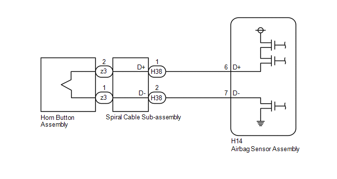
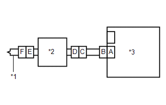
WIRING DIAGRAM
CAUTION / NOTICE / HINT
NOTICE:
After turning the ignition switch off, waiting time may be required before disconnecting the cable from the negative (-) auxiliary battery terminal.
Click here

HINT:
-
To perform the simulation method, select Check Mode with the GTS.
Click here

-
Perform the simulation method while checking the Data List.
Click here

-
When disconnecting and reconnecting the cable to the auxiliary battery terminal, there is an automatic learning function that completes learning when the respective system is used.
Click here

PROCEDURE
| 1. | CHECK CURRENT DTC |
(a) Turn the ignition switch to ON, and wait for at least 60 seconds.
(b) Check for DTCs.
Body Electrical > SRS Airbag > Trouble Codes| Result | Proceed to |
|---|---|
| Current B000113 is output | A |
| History B000113 is output | B |
| B |
 | USE SIMULATION METHOD TO CHECK |
|

| 2. | CHECK CONNECTION OF CONNECTORS |
(a) Turn the ignition switch off.
(b) Disconnect the cable from the negative (-) auxiliary battery terminal.
CAUTION:
Wait at least 60 seconds after disconnecting the cable from the negative (-) auxiliary battery terminal to disable the SRS system.
(c) Check that the connectors are properly connected to the horn button assembly, spiral cable sub-assembly and airbag sensor assembly.
OK:
The connectors are properly connected.
| NG |
 | CONNECT CONNECTORS PROPERLY |
|

| 3. | CHECK CONNECTORS |
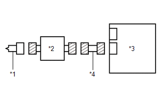
| (a) Disconnect the connectors from the horn button assembly, spiral cable sub-assembly and airbag sensor assembly. |
|
(b) Check that the terminals of the connectors are not deformed or damaged.
OK:
The terminals of the connectors are not deformed or damaged.
(c) Check that the short springs of the activation prevention mechanisms of the wire harness connector and spiral cable sub-assembly connector are not deformed or damaged.
OK:
The short springs are not deformed or damaged.
| NG |
 | REPLACE SPIRAL CABLE SUB-ASSEMBLY OR REPAIR OR REPLACE WIRE HARNESS |
|

| 4. | CHECK HORN BUTTON ASSEMBLY |
| (a) Connect the connectors to the airbag sensor assembly and spiral cable sub-assembly. |
|
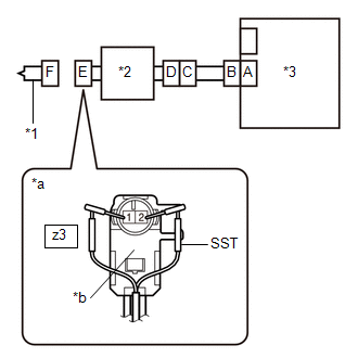
(b) Connect the white wire side of SST (resistance 2.1 Ω) to connector E (light green connector).
CAUTION:
Never connect a tester to the horn button assembly for measurement, as this may lead to a serious injury due to airbag deployment.
NOTICE:
- Do not forcibly insert SST into the terminals of the connector when connecting it.
- Insert SST straight into the terminals of the connector.
SST: 09843-18061
(c) Connect the cable to the negative (-) auxiliary battery terminal.
(d) Turn the ignition switch to ON, and wait for at least 60 seconds.
(e) Clear the DTCs stored in memory.
Body Electrical > SRS Airbag > Clear DTCs(f) Turn the ignition switch off.
|

| 5. | CHECK HORN BUTTON ASSEMBLY |
(a) Turn the ignition switch to ON, and wait for at least 60 seconds.
(b) Check for DTCs.
Body Electrical > SRS Airbag > Trouble CodesHINT:
Codes other than DTC B000113 may be output at this time, but they are not related to this check.
| Result | Proceed to |
|---|---|
| B000113 is not output | A |
| B000113 is output | B |
(c) Turn the ignition switch off.
(d) Disconnect the cable from the negative (-) auxiliary battery terminal.
CAUTION:
Wait at least 60 seconds after disconnecting the cable from the negative (-) auxiliary battery terminal to disable the SRS system.
(e) Disconnect SST from connector E.
| A |
 | REPLACE HORN BUTTON ASSEMBLY |
|

| 6. | CHECK DRIVER SEAT AIRBAG SQUIB CIRCUIT (OPEN) |
| (a) Disconnect the connector from the airbag sensor assembly. |
|
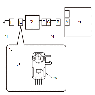
(b) Measure the resistance according to the value(s) in the table below.
Standard Resistance:
| Tester Connection | Condition | Specified Condition |
|---|---|---|
| z3-2 - z3-1 | Always | Below 1 Ω |
| NG |
 | GO TO STEP 9 |
|

| 7. | CLEAR DTC |
| (a) Connect the connectors to the horn button assembly and airbag sensor assembly. |
|
(b) Connect the cable to the negative (-) auxiliary battery terminal.
(c) Turn the ignition switch to ON, and wait for at least 60 seconds.
(d) Clear the DTCs stored in memory.
Body Electrical > SRS Airbag > Clear DTCs(e) Turn the ignition switch off.
|

| 8. | CHECK DTC |
(a) Turn the ignition switch to ON, and wait for at least 60 seconds.
(b) Check for DTCs.
Body Electrical > SRS Airbag > Trouble CodesHINT:
Codes other than DTC B000113 may be output at this time, but they are not related to this check.
| Result | Proceed to |
|---|---|
| B000113 is not output | A |
| B000113 is output | B |
| A |
 | USE SIMULATION METHOD TO CHECK |
| B |
 | REPLACE AIRBAG SENSOR ASSEMBLY |
| 9. | CHECK WIRE HARNESS (OPEN) |
| (a) Disconnect the connector from the spiral cable sub-assembly. |
|
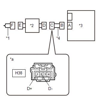
(b) Measure the resistance according to the value(s) in the table below.
Standard Resistance:
| Tester Connection | Condition | Specified Condition |
|---|---|---|
| H38-1 (D+) - H38-2 (D-) | Always | Below 1 Ω |
| OK |
 | REPLACE SPIRAL CABLE SUB-ASSEMBLY |
| NG |
 | REPAIR OR REPLACE HARNESS OR CONNECTOR |
 Driver Frontal Stage 1 Deployment Control Circuit Short to Battery (B000112)
DESCRIPTION DTC No. Detection Item DTC Detection Condition Trouble Area Warning Indicate Test Mode / Check Mode B000112 Driver Frontal Stage 1 Deployment Control Circuit Short to Battery
The airbag sensor assembly detects a short to B+ in the driver seat airbag squib circuit for 0...
 Driver Frontal Stage 1 Deployment Control Circuit Resistance Below Threshold (B00011A)
DESCRIPTION DTC No. Detection Item DTC Detection Condition Trouble Area Warning Indicate Test Mode / Check Mode B00011A Driver Frontal Stage 1 Deployment Control Circuit Resistance Below Threshold
The airbag sensor assembly detects a line short in the driver seat airbag squib circuit for 2 seconds during the primary check
Spiral cable sub-assembly malfunction
Horn button assembly malfunction
Airbag sensor assembly malfunction
Harness or connector
Spiral cable sub-assembly
Horn button assembly
Airbag sensor assembly
Comes on Applies to check mode WIRING DIAGRAM
CAUTION / NOTICE / HINT NOTICE: After turning the ignition switch off, waiting time may be required before disconnecting the cable from the negative (-) auxiliary battery terminal...
Other information:
Toyota Yaris XP210 (2020-2024) Reapir and Service Manual: Weak Blower Output
DESCRIPTION If the airflow from the front registers is weak regardless of the blower speed setting displayed on the air conditioning control assembly, the following factors may be the cause. Symptom Factor Airflow volume is constantly low Airflow volume sometimes becomes low ECO mode control of air conditioning system is enabled Harness or connector Air conditioning amplifier assembly Blower motor with fan sub-assembly malfunction Clogged clean air filter Clogged No...
Toyota Yaris XP210 (2020-2024) Owner's Manual: Operating Tips for WMA
WMA is short for Windows Media Audio and is the audio compression format used by Microsoft. Audio data can be created and stored at a higher compression ratio than MP3. This unit plays files with the extension (.wma) as WMA files. *: Microsoft and Windows Media are registered trademarks of Microsoft Corporation U...
Categories
- Manuals Home
- Toyota Yaris Owners Manual
- Toyota Yaris Service Manual
- To Set Speed
- Removal
- Immobilizer System
- New on site
- Most important about car
Fuel Gauge
The fuel gauge shows approximately how much fuel is remaining in the tank when the ignition is switched ON. We recommend keeping the tank over 1/4 full.
