Toyota Yaris: Cylinder Head / Reassembly
REASSEMBLY
PROCEDURE
1. INSTALL SPARK PLUG TUBE
HINT:
When using a new cylinder head sub-assembly, the spark plug tubes must be replaced.
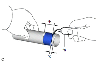
| (a) Apply adhesive to a new spark plug tube as shown in the illustration. Adhesive: Toyota Genuine Adhesive 1324, Three Bond 1324 or equivalent Standard Application Width: 1.0 to 7.0 mm (0.0394 to 0.276 in.) Distance: 1.0 mm (0.0394 in.) NOTICE:
|
|
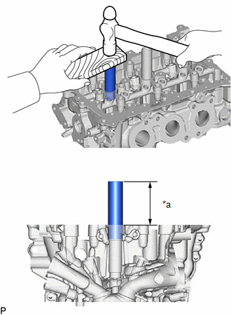
| (b) Using a wooden block and hammer, tap in the 4 spark plug tubes to the specified protrusion height. Standard Protrusion Height: 70.5 to 71.5 mm (2.78 to 2.81 in.) NOTICE: To avoid tapping in the spark plug tube too far, measure the protrusion height while tapping it. |
|
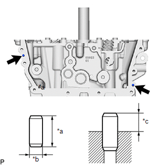
2. INSTALL STUD BOLT
NOTICE:
If a stud bolt is deformed or its threads are damaged, replace it.
| (a) Using an E8 "TORX" socket wrench, install the 7 stud bolts. Torque: 19.5 N·m {199 kgf·cm, 14 ft·lbf} |
|
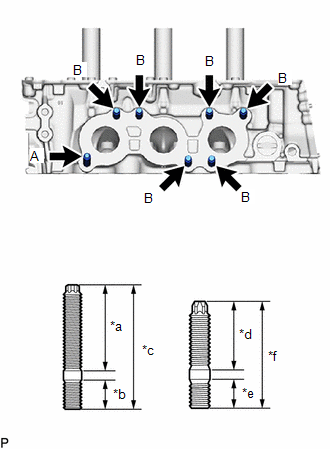
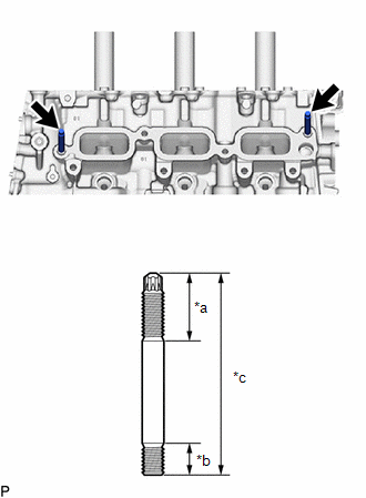
| (b) Using an E8 "TORX" socket wrench, install the 2 stud bolts. |
|
3. INSTALL STRAIGHT PIN
| (a) Using a plastic hammer, tap in 2 new straight pins to the cylinder head sub-assembly. Standard Protrusion Height: 3.0 to 5.0 mm (0.118 to 0.197 in.) |
|
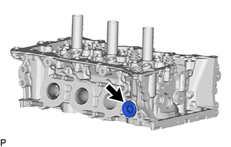
4. INSTALL NO. 2 STRAIGHT SCREW PLUG
HINT:
If coolant leaks from a No. 2 straight screw plug or a plug is corroded, replace it.
(a) Apply adhesive to the No. 2 straight screw plug.
Adhesive:
Toyota Genuine Adhesive 1324, Three Bond 1324 or equivalent
NOTICE:
Install the No. 2 straight screw plug within 3 minutes of applying adhesive.
| (b) Using a 10 mm straight hexagon wrench, install the No. 2 straight screw plug to the cylinder head sub-assembly. Torque: 135 N·m {1377 kgf·cm, 100 ft·lbf} |
|
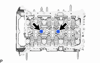
5. INSTALL NO. 1 STRAIGHT SCREW PLUG
HINT:
If coolant leaks from a No. 1 straight screw plug or a plug is corroded, replace it.
(a) Apply adhesive to the 3 No. 1 straight screw plugs.
Adhesive:
Toyota Genuine Adhesive 1324, Three Bond 1324 or equivalent
NOTICE:
Install the No. 1 straight screw plug within 3 minutes of applying adhesive.
| (b) Using a 6 mm straight hexagon wrench, install the 3 No. 1 straight screw plugs to the cylinder head sub-assembly. Torque: 25 N·m {255 kgf·cm, 18 ft·lbf} |
|
6. INSTALL VALVE SPRING SEAT
(a) Install the 12 valve spring seats to the cylinder head sub-assembly.
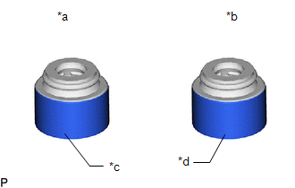
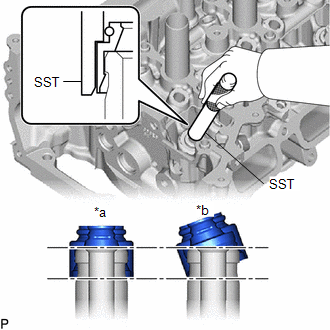
7. INSTALL VALVE STEM OIL SEAL
| (a) Apply a light coat of engine oil to 12 new valve stem oil seals. NOTICE: Make sure to install each valve stem oil seal to the correct side. Installing an intake valve stem oil seal to the exhaust side or installing an exhaust valve stem oil seal to the intake side can cause installation problems later. HINT: The intake valve stem oil seals are gold and the exhaust valve stem oil seals are gray. |
|
| (b) Using SST, push in the 12 valve stem oil seals. SST: 09201-41020 NOTICE:
|
|
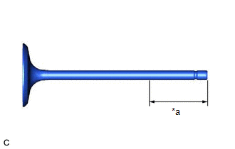
8. INSTALL INTAKE VALVE
| (a) Sufficiently apply engine oil to the tip area of the intake valve shown in the illustration. |
|
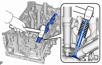
(b) Install the 6 intake valves, 6 compression springs and 6 valve spring retainers to the cylinder head sub-assembly.
NOTICE:
Install the same parts in the same combination to their original locations.
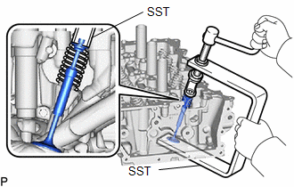
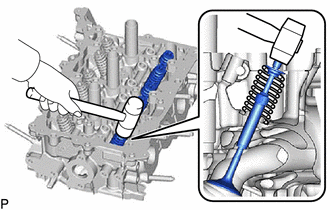
| (c) Using SST, compress each compression spring and install the 6 valve spring retainer locks. SST: 09202-70020 09202-01010 09202-01020 SST: 09202-00021 |
|
| (d) Using a plastic hammer, lightly tap the valve stem tip to ensure a proper fit. NOTICE:
|
|
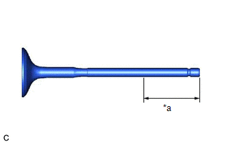
9. INSTALL EXHAUST VALVE
| (a) Sufficiently apply engine oil to the tip area of the exhaust valve shown in the illustration. |
|
(b) Install the 6 exhaust valves, 6 compression springs and 6 valve spring retainers to the cylinder head sub-assembly.
NOTICE:
Install the same parts in the same combination to their original locations.
| (c) Using SST, compress each compression spring and install the 6 valve spring retainer locks. SST: 09202-70020 09202-01010 09202-01020 SST: 09202-00021 |
|

| (d) Using a plastic hammer, lightly tap the valve stem tip to ensure a proper fit. NOTICE:
|
|
 Replacement
REPLACEMENT PROCEDURE 1. REPLACE INTAKE VALVE GUIDE BUSH (a) Heat the cylinder head sub-assembly to between 80 and 100°C (176 to 212°F). (b) Place the cylinder head sub-assembly on wooden blocks...
 Repair
REPAIR PROCEDURE 1. REPAIR INTAKE VALVE SEAT NOTICE:
While repairing the intake valve seat, make sure to constantly check the valve seat width and valve seating position...
Other information:
Toyota Yaris XP210 (2020-2026) Reapir and Service Manual: Components
C..
Toyota Yaris XP210 (2020-2026) Reapir and Service Manual: Customize Parameters
CUSTOMIZE PARAMETERS CUSTOMIZE SEAT BELT WARNING SYSTEM NOTICE: When the customer requests a change in a function, first make sure that the function can be customized. Be sure to make a note of the current settings before customizing. When troubleshooting a function, first make sure that the function is set to the default setting...
Categories
- Manuals Home
- Toyota Yaris Owners Manual
- Toyota Yaris Service Manual
- To Set Speed
- Headlights
- Engine & Hybrid System
- New on site
- Most important about car
Supplemental Restraint System (SRS) Precautions
The front and side supplemental restraint systems (SRS) include different types of air bags. Please verify the different types of air bags which are equipped on your vehicle by locating the “SRS AIRBAG” location indicators. These indicators are visible in the area where the air bags are installed.
The air bags are installed in the following locations:
The steering wheel hub (driver air bag) The front passenger dashboard (front passenger air bag) The outboard sides of the front seatbacks (side air bags) The front and rear window pillars, and the roof edge along both sides (curtain air bags)