Toyota Yaris: Fuel Pump / Reassembly
REASSEMBLY
PROCEDURE
1. INSTALL FUEL PUMP
HINT:
Perform "Inspection After Repair" after replacing the fuel pump.
Click here

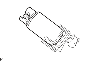
| (a) Install the fuel pump to the No. 1 cap. |
|
(b) Apply gasoline to a new O-ring.
| (c) Install the O-ring to the sub-assembly support. |
|
(d) Attach the 3 claws and install the No. 1 cap to the sub-assembly support.
(e) Connect the connector to the fuel pump.
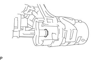
(f) Attach the 4 claws and connect the sub-assembly support to the fuel sub-tank sub-assembly.
(g) Apply gasoline to a new O-ring.
| (h) Install the O-ring to the fuel suction tube. |
|
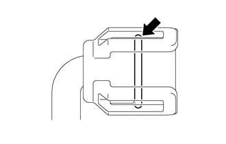
(i) Attach the 2 claws and 2 clamps and connect the fuel suction tube to the fuel sub-tank sub-assembly.
2. INSTALL FUEL SENDER GAUGE ASSEMBLY
Click here

 Inspection
INSPECTION PROCEDURE 1. INSPECT FUEL PUMP (a) Measure the resistance according to the value(s) in the table below. Standard Resistance: Tester Connection Specified Condition U - V 0...
 Installation
INSTALLATION PROCEDURE 1. INSTALL FUEL SUCTION WITH PUMP AND GAUGE TUBE ASSEMBLY (a) Install a new gasket to the fuel tank assembly. (b) Connect the fuel return vent tube sub-assembly to the fuel suction tube with pump and gauge assembly...
Other information:
Toyota Yaris XP210 (2020-2026) Reapir and Service Manual: Disassembly
DISASSEMBLY PROCEDURE 1. REMOVE STEERING RACK BOOT CLIP (for LH Side) (a) Using pliers, remove the steering rack boot clip. 2. REMOVE STEERING RACK BOOT CLIP (for RH Side) HINT: Perform the same procedure as for the LH side. 3. REMOVE NO. 2 STEERING RACK BOOT CLAMP (a) Using a screwdriver, remove the No...
Toyota Yaris XP210 (2020-2026) Reapir and Service Manual: EPS Warning Light Circuit
DESCRIPTION Use the following procedure if no DTCs are output but the EPS warning light is illuminated continuously. The power steering ECU assembly controls the warning light in the combination meter assembly via CAN communication. CAUTION / NOTICE / HINT NOTICE: When the power steering ECU assembly has been replaced, perform Power Steering ECU Initial Setting (assist map writing)...
Categories
- Manuals Home
- Toyota Yaris Owners Manual
- Toyota Yaris Service Manual
- Battery Monitor Module General Electrical Failure (P058A01)
- Maintenance
- Opening and Closing the Liftgate/Trunk Lid
- New on site
- Most important about car
Key Suspend Function
If a key is left in the vehicle, the functions of the key left in the vehicle are temporarily suspended to prevent theft of the vehicle.
To restore the functions, press the unlock button on the functions-suspended key in the vehicle.