Toyota Yaris: Front Disc Brake Pad / Removal
REMOVAL
CAUTION / NOTICE / HINT
NOTICE:
After replacing the front disc brake pads, the brake pedal may feel soft due to clearance between the front disc brake pads and front disc. Depress the brake pedal several times until the brake pedal feels firm.
HINT:
- Use the same procedure for the RH side and LH side.
- The following procedure is for the LH side.
PROCEDURE
1. REMOVE FRONT WHEEL
Click here

2. REMOVE FRONT DISC BRAKE PIN HOLD CLIP
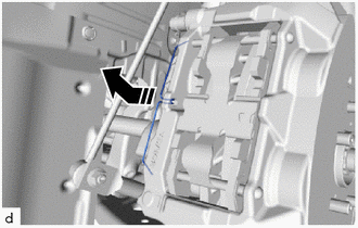
| (a) Disengage the hook from the front disc brake cylinder assembly and remove the front disc brake pin hold clip from the 2 front disc brake anti-rattle pins. |
|
3. REMOVE FRONT DISC BRAKE ANTI-RATTLE PIN
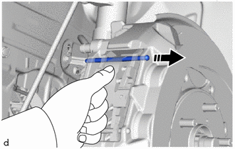
| (a) While pressing the front disc brake anti-rattle spring, remove the front disc brake anti-rattle pin (upper side). |
|
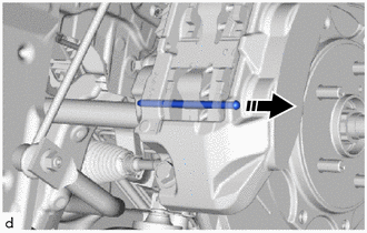
| (b) Disengage the front disc brake anti-rattle spring from the front disc brake pads and remove the front disc brake anti-rattle pin (lower side). |
|
4. REMOVE FRONT DISC BRAKE ANTI-RATTLE SPRING
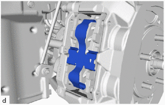
| (a) Remove the front disc brake anti-rattle spring. |
|
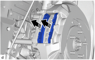
5. REMOVE FRONT DISC BRAKE PAD
NOTICE:
Be sure to inspect the front disc when replacing the front disc brake pads with new ones.
Click here

| (a) Remove the 2 front disc brake pads from the front disc brake cylinder assembly. |
|
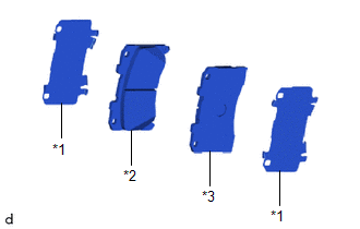
6. REMOVE FRONT DISC BRAKE ANTI-SQUEAL SHIM KIT
| (a) Remove the 2 front disc brake anti-squeal shims from each front disc brake pad. |
|
 Components
C..
 Installation
INSTALLATION CAUTION / NOTICE / HINT HINT:
Use the same procedure for the RH side and LH side.
The following procedure is for the LH side.
PROCEDURE 1...
Other information:
Toyota Yaris XP210 (2020-2026) Reapir and Service Manual: Charge Air Cooler Temperature Sensor Bank 1 Circuit Short to Ground (P007A11)
DESCRIPTION The intake air temperature sensor, built into the No. 2 turbo pressure sensor, monitors the intake air temperature. The intake air temperature sensor has a built-in thermistor with a resistance that varies according to the temperature of the intake air...
Toyota Yaris XP210 (2020-2026) Reapir and Service Manual: Meter Illumination is Always Dark
DESCRIPTION The combination meter assembly receives signals from this circuit to adjust the illumination of the combination meter assembly. The combination meter assembly sets the illumination level based on the user operation of the light control rheostat...
Categories
- Manuals Home
- Toyota Yaris Owners Manual
- Toyota Yaris Service Manual
- Engine Start Function When Key Battery is Dead
- How to connect USB port/Auxiliary jack
- Fuse Panel Description
- New on site
- Most important about car
Supplemental Restraint System (SRS) Precautions
The front and side supplemental restraint systems (SRS) include different types of air bags. Please verify the different types of air bags which are equipped on your vehicle by locating the “SRS AIRBAG” location indicators. These indicators are visible in the area where the air bags are installed.
The air bags are installed in the following locations:
The steering wheel hub (driver air bag) The front passenger dashboard (front passenger air bag) The outboard sides of the front seatbacks (side air bags) The front and rear window pillars, and the roof edge along both sides (curtain air bags)