
Toyota Yaris: Rear Differential Carrier Oil Seal / Replacement
REPLACEMENT
CAUTION / NOTICE / HINT
The necessary procedures (adjustment, calibration, initialization, or registration) that must be performed after parts are removed and installed, or replaced during diaphragm oil seal replacement are shown below.
Necessary Procedure After Parts Removed/Installed/Replaced| Replaced Part or Performed Procedure | Necessary Procedure | Effect/Inoperative Function when Necessary Procedure not Performed | Link |
|---|---|---|---|
| Gas leaks from exhaust system | Inspection after repair |
|
|
| Rear wheel alignment adjustment | ECU Data Initialization | Active torque split AWD system |
|
| Calibration |
|
|


CAUTION:
-
To prevent burns, do not touch the engine, exhaust pipe or other high temperature components while the engine is hot.
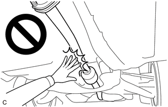
-
The rear differential carrier assembly is very heavy. Be sure to follow the procedure described in the repair manual, or the engine lifter may suddenly drop or the rear differential carrier assembly may fall off the engine lifter.
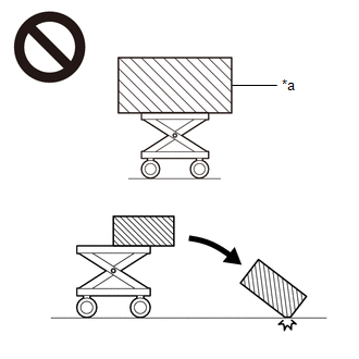
*a
An Object Exceeding Weight Limit of Engine Lifter
PROCEDURE
1. REMOVE REAR DIFFERENTIAL CARRIER ASSEMBLY
Click here

2. SEPARATE ELECTRO MAGNETIC CONTROL COUPLING WIRE HARNESS
Click here

3. REMOVE ELECTRO MAGNETIC CONTROL COUPLING SUB-ASSEMBLY
Click here

4. REMOVE TRANSMISSION COUPLING CONICAL SPRING WASHER
Click here

5. REMOVE TRANSMISSION COUPLING SPACER
Click here

6. REMOVE DIAPHRAGM OIL SEAL
| (a) Using SST, remove the diaphragm oil seal from the rear differential carrier assembly. SST: 09308-00010 |
|
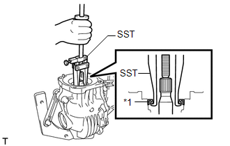
7. INSTALL DIAPHRAGM OIL SEAL
| (a) Using SST and a press, install a new diaphragm oil seal into the rear differential carrier assembly. SST: 09506-35010 SST: 09554-22010 NOTICE:
Standard Distance (A): 0.7 to 1.3 mm (0.0276 to 0.0511 in.) |
|
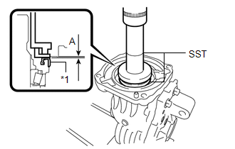
(b) Apply a light coat of MP grease to the lip of the new diaphragm oil seal.
8. INSTALL TRANSMISSION COUPLING SPACER
Click here

9. INSTALL TRANSMISSION COUPLING CONICAL SPRING WASHER
Click here

10. INSTALL ELECTRO MAGNETIC CONTROL COUPLING SUB-ASSEMBLY
Click here

11. INSTALL ELECTRO MAGNETIC CONTROL COUPLING WIRE HARNESS
Click here

12. INSTALL REAR DIFFERENTIAL CARRIER ASSEMBLY
Click here

 Components
COMPONENTS ILLUSTRATION
*1 DIAPHRAGM OIL SEAL *2 ELECTRO MAGNETIC CONTROL COUPLING SUB-ASSEMBLY *3 ELECTRO MAGNETIC CONTROL COUPLING WIRE HARNESS *4 TRANSMISSION COUPLING CONICAL SPRING WASHER *5 TRANSMISSION COUPLING SPACER *6 REAR DIFFERENTIAL DRAIN PLUG *7 REAR DIFFERENTIAL FILLER PLUG *8 GASKET *9 REAR DIFFERENTIAL CARRIER ASSEMBLY - -
Tightening torque for "Major areas involving basic vehicle performance such as moving/turning/stopping" : N*m (kgf*cm, ft...
 Rear Differential Side Gear Shaft Oil Seal
ComponentsCOMPONENTS ILLUSTRATION
*1 REAR DRIVE SHAFT OIL SEAL *2 REAR DIFFERENTIAL FILLER PLUG *3 REAR DIFFERENTIAL DRAIN PLUG *4 REAR DIFFERENTIAL CARRIER ASSEMBLY *5 GASKET - -
Tightening torque for "Major areas involving basic vehicle performance such as moving/turning/stopping" : N*m (kgf*cm, ft...
Other information:
Toyota Yaris XP210 (2020-2026) Reapir and Service Manual: Data List / Active Test
DATA LIST / ACTIVE TEST DATA LIST (a) Perform the Active Test according to the display on the GTS. Body Electrical > Power Distribution Box > Data List Tester Display Measurement Item Range Normal Condition Diagnostic Note Rear Defogger Input Signal Window defogger switch signal input condition ON or OFF ON: Window defogger switch is on OFF: Window defogger switch is off - Rear Defogger Output Signal Window defogger output condition ON or OFF ON: Window defogger operates OFF: Window defogger does not operate - Rear Defogger Output Current Window defogger current Min...
Toyota Yaris XP210 (2020-2026) Reapir and Service Manual: Starter Signal Circuit
DESCRIPTION While the engine is being cranked, current flows from terminal STAR of the certification ECU (smart key ECU assembly) to the clutch start switch assembly and to terminal STA of the ECM (STA signal). WIRING DIAGRAM Refer to DTC P061512. Click here CAUTION / NOTICE / HINT NOTICE: Inspect the fuses for circuits related to this system before performing the following procedure...
Categories
- Manuals Home
- Toyota Yaris Owners Manual
- Toyota Yaris Service Manual
- Adjustment
- To Set Speed
- G16e-gts (engine Mechanical)
- New on site
- Most important about car
Turning the Engine Off
Stop the vehicle completely. Manual transaxle: Shift into neutral and set the parking brake.Automatic transaxle: Shift the selector lever to the P position and set the parking brake.
Press the push button start to turn off the engine. The ignition position is off.