Toyota Yaris: Power Window Regulator Motor / Inspection
INSPECTION
CAUTION / NOTICE / HINT
NOTICE:
- Do not apply positive (+) auxiliary battery voltage to any terminals, except terminal K7-2 (B) or L7-2 (B), to avoid damaging the pulse sensor inside the motor.
-
Perform initialization of the power window system after removing, inspecting or replacing the power window regulator motor assembly.
Click here
.gif)
PROCEDURE
1. INSPECT POWER WINDOW REGULATOR MOTOR ASSEMBLY RH
(a) Connect a positive (+) auxiliary battery lead to connector terminal K7-2 (B).
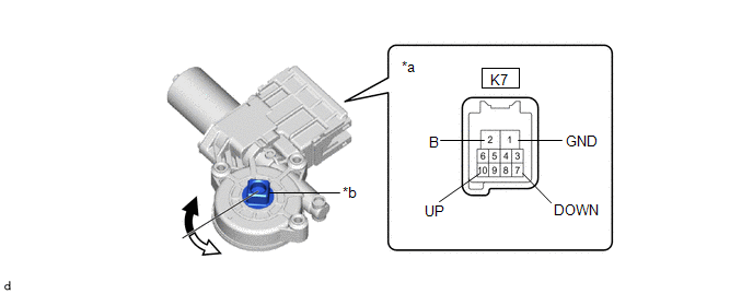
| *a | Component without harness connected (Power Window Regulator Motor Assembly RH) | *b | Motor Gear |
.png) | Clockwise |
.png) | Counterclockwise |
NOTICE:
Do not connect a positive (+) auxiliary battery lead to any terminals other than terminal K7-2 (B) to avoid damaging the pulse sensor inside the motor.
(b) Connect a negative (-) auxiliary battery lead to connector terminals K7-1 (GND) and K7-7 (DOWN) or K7-10 (UP).
(c) Check that the motor gear rotates smoothly as follows:
OK:
| Measurement Condition | Specified Condition |
|---|---|
| Motor gear rotates clockwise |
| Motor gear rotates counterclockwise |
- If the result is not as specified, replace the power window regulator motor assembly RH.
2. INSPECT POWER WINDOW REGULATOR MOTOR ASSEMBLY LH
(a) Connect a positive (+) auxiliary battery lead to connector terminal L7-2 (B).
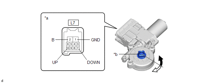
| *a | Component without harness connected (Power Window Regulator Motor Assembly LH) | *b | Motor Gear |
|
| Counterclockwise |
| Clockwise |
NOTICE:
Do not connect a positive (+) auxiliary battery lead to any terminals other than terminal L7-2 (B) to avoid damaging the pulse sensor inside the motor.
(b) Connect a negative (-) auxiliary battery lead to connector terminals L7-1 (GND) and L7-7 (DOWN) or L7-10 (UP).
(c) Check that the motor gear rotates smoothly as follows:
OK:
| Measurement Condition | Specified Condition |
|---|---|
| Motor gear rotates counterclockwise |
| Motor gear rotates clockwise |
- If the result is not as specified, replace the power window regulator motor assembly LH.
 Removal
REMOVAL CAUTION / NOTICE / HINT The necessary procedures (adjustment, calibration, initialization or registration) that must be performed after parts are removed and installed, or replaced during the power window regulator motor removal/installation are shown below...
 Installation
INSTALLATION PROCEDURE 1. INSTALL POWER WINDOW REGULATOR MOTOR ASSEMBLY (a) Apply MP grease to the sliding and rotating areas of the power window regulator motor assembly...
Other information:
Toyota Yaris XP210 (2020-2026) Reapir and Service Manual: Check For Intermittent Problems
CHECK FOR INTERMITTENT PROBLEMS NOTICE: If the vehicle or vehicle controls are operated (for example, during initial inspection when the vehicle is brought in for repair) before Vehicle Control History (RoB) has been collected, the past Vehicle Control History (RoB) information could be lost...
Toyota Yaris XP210 (2020-2026) Reapir and Service Manual: Differential Oil Seal (for Lh Side)
ComponentsCOMPONENTS ILLUSTRATION *1 FRONT DRIVE SHAFT OIL SEAL LH - - ● Non-reusable part MP grease ReplacementREPLACEMENT CAUTION / NOTICE / HINT The necessary procedures (adjustment, calibration, initialization or registration) that must be performed after parts are removed and installed, or replaced during the front drive shaft oil seal LH removal/installation are shown below...
Categories
- Manuals Home
- Toyota Yaris Owners Manual
- Toyota Yaris Service Manual
- Adjustment
- Key Battery Replacement
- Fuel Gauge
- New on site
- Most important about car
Front Seat Belt Pretensioners
The front seat belt pretensioners are designed to deploy in moderate or severe frontal, near frontal collisions.
In addition, the pretensioners operate when a side collision or a rollover accident is detected. The pretensioners operate differently depending on what types of air bags are equipped. For more details about the seat belt pretensioner operation, refer to the SRS Air Bag Deployment Criteria.