Toyota Yaris: Knock Sensor / Installation
INSTALLATION
CAUTION / NOTICE / HINT
NOTICE:
This procedure includes the installation of small-head bolts. Refer to Small-Head Bolts of Basic Repair Hint to identify the small-head bolts.
Click here

PROCEDURE
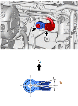
1. INSTALL KNOCK SENSOR
| (a) Install the knock sensor to the cylinder block sub-assembly with the bolt so that the knock sensor installation position is as shown in the illustration. Torque: 21 N·m {214 kgf·cm, 15 ft·lbf} NOTICE:
|
|
(b) Connect the knock sensor connector.
2. INSTALL NO. 1 VENTILATION CASE
Click here

3. INSTALL NO. 2 CYLINDER BLOCK INSULATOR
Click here

4. INSTALL NO. 2 WATER BY-PASS PIPE
Click here

5. CONNECT NO. 6 WATER BY-PASS HOSE
(a) Connect the No. 6 water by-pass hose and slide the clip to secure it.
6. INSTALL NO. 4 WATER BY-PASS HOSE
(a) Connect the No. 4 water by-pass hose and slide the clip to secure it.
7. INSTALL INTAKE MANIFOLD
Click here

8. PERFORM INITIALIZATION
(a) Perform "Inspection After Repair" after replacing the knock sensor.
Click here

 Inspection
INSPECTION PROCEDURE 1. INSPECT KNOCK SENSOR (a) Measure the resistance according to the value(s) in the table below. Standard Resistance: Tester Connection Condition Specified Condition e1-1 - e1-2 25°C (77°F) 120 to 280 kΩ If the result is not as specified, replace the knock sensor...

Other information:
Toyota Yaris XP210 (2020-2026) Reapir and Service Manual: Automatic High Beam Switch Indicator does not Come ON
DESCRIPTION When the automatic high beam system is on, the main body ECU (multiplex network body ECU) illuminates the auto high beam switch indicator. WIRING DIAGRAM CAUTION / NOTICE / HINT NOTICE: Inspect the fuses for circuits related to this system before performing the following procedure...
Toyota Yaris XP210 (2020-2026) Reapir and Service Manual: Operation Check
OPERATION CHECK CHECK FRONT WIPER CONTROL (a) Auto wiper function (1) Continuously apply water to the windshield glass in front of the rain sensor. (2) Turn the ignition switch to ON. (3) Move the front wiper switch to the AUTO position. (4) Check that the front wipers operate...
Categories
- Manuals Home
- Toyota Yaris Owners Manual
- Toyota Yaris Service Manual
- Engine & Hybrid System
- Battery Monitor Module General Electrical Failure (P058A01)
- Brake System Control Module "A" System Voltage System Voltage Low (C137BA2)
- New on site
- Most important about car
Front Seat Belt Pretensioners
The front seat belt pretensioners are designed to deploy in moderate or severe frontal, near frontal collisions.
In addition, the pretensioners operate when a side collision or a rollover accident is detected. The pretensioners operate differently depending on what types of air bags are equipped. For more details about the seat belt pretensioner operation, refer to the SRS Air Bag Deployment Criteria.