
Toyota Yaris: Networking / Network Gateway Ecu
Toyota Yaris XP210 (2020-2026) Reapir and Service Manual / Power Source & Network / Networking / Network Gateway Ecu
 Power Source Control System Missing Message (B278C87)
DESCRIPTION When an internal malfunction is detected in the certification ECU (smart key ECU assembly), this DTC is stored. DTC No. Detection Item DTC Detection Condition Trouble Area B278C87 Power Source Control System Missing Message An internal malfunction occurs in the certification ECU (smart key ECU assembly)...
 Components
COMPONENTS ILLUSTRATION
*1 COWL SIDE TRIM BOARD RH *2 FRONT DOOR SCUFF PLATE RH *3 FRONT DOOR OPENING TRIM WEATHERSTRIP RH *4 GLOVE COMPARTMENT DOOR ASSEMBLY *5 LOWER NO...
Other information:
Toyota Yaris XP210 (2020-2026) Reapir and Service Manual: Terminals Of Ecu
TERMINALS OF ECU TERMINALS OF ECU *a Component without harness connected (Skid Control ECU [Brake Actuator Assembly]) - - Terminal No. (Symbol) Terminal Description 1 (GND2) Pump motor ground 2 - (Not used) 3 - (Not used) 4 - (Not used) 5 (STP2) Stop light switch assembly input 6 - (Not used) 7 - (Not used) 8 - (Not used) 9 - (Not used) 10 (CANL) CAN communication line L 11 - (Not used) 12 (IGR) ECU power supply input 13 (BM) Motor relay power supply 14 (SP1) Speed signal output for speedometer 15 (RR-) Rear wheel speed RH (-) signal input 16 (RR+) Rear wheel speed RH (+) power supply output 17 (FL-) Front wheel speed LH (-) signal input 18 (FL+) Front wheel speed LH (+) power supply output 19 - (Not used) 20 - (Not used) 21 - (Not used) 22 (CANH) CAN communication line H 23 - (Not used) 24 - (Not used) 25 (GND1) Skid control ECU (brake actuator assembly) ground 26 (STPO) Stop light switch assembly output 27 - (Not used) 28 (RL-) Rear wheel speed LH (-) signal input 29 (RL+) Rear wheel speed LH (+) power supply output 30 (FR-) Front wheel speed RH (-) signal input 31 (FR+) Front wheel speed RH (+) power supply output 32 - (Not used) 33 (CSW) VSC OFF switch (combination switch assembly) input 34 - (Not used) 35 (STP) Stop light switch assembly input 36 (CA2H) CAN communication line H 37 (CA2L) CAN communication line L 38 (+BS) Solenoid relay power supply TERMINAL INSPECTION (a) Disconnect the A108 connector and measure the voltage or resistance on the wire harness side...
Toyota Yaris XP210 (2020-2026) Reapir and Service Manual: Diagnosis System
DIAGNOSIS SYSTEM FUNCTION OF WARNING INDICATOR AND MESSAGE (a) If the pre-collision system is not functioning properly, the driver is warned by the PCS warning light and a warning message is displayed on the multi-information display. Warning Message Detail DTC/RoB PCS warning light "Pre-Collision System Malfunction Visit Your Dealer" Pre-collision system malfunctioning Stored Illuminates "Pre-Collision System Radar In Self Calibration Unavailable See Owner's Manual" Millimeter wave radar sensor assembly misaligned Stored Illuminates "Pre-Collision System Out of Temperature Range Unavailable See Owner's Manual" Millimeter wave radar sensor assembly temperature malfunction Stored Illuminates "Pre-Collision System Unavailable See Owner's Manual" Millimeter wave radar sensor assembly voltage malfunction Determination was made for temporary suspension of system operation due to millimeter wave radar sensor assembly detecting interference from other nearby radar emitters Stored Illuminates "Pre-Collision System Radar Sensor Blocked Unavailable Clean Radar Sensor" Foreign matter attached to millimeter wave radar sensor assembly Stored Illuminates "Front Camera Unavailable See Owner's Manual" Abnormal forward recognition camera voltage Stored Illuminates "Front Camera Out of Temperature Range Unavailable Wait until Normal Temperature" Forward recognition camera temperature outside of operational range Stored Illuminates "Front Camera Low Visibility Unavailable See Owner's Manual" Foreign matter attached to forward recognition camera or area of windshield in front of forward recognition camera Forward recognition camera or area of windshield in front of forward recognition camera is fogged up Stored Illuminates "VSC Turned Off Pre-Collision Brake System Unavailable" VSC system is disabled Not stored Illuminates PCS Warning Light Illumination Status PCS Warning Light Condition Illuminates Pre-collision system malfunctioning Pre-collision system temporarily disabled During pre-collision system radar alignment Pre-collision system disabled VSC system disabled Not illuminated Other INITIAL CHECK (a) An initial check is performed when the ignition switch is off for more than 2 seconds and then turned ON...
Categories
- Manuals Home
- Toyota Yaris Owners Manual
- Toyota Yaris Service Manual
- Headlights
- Power Integration No.1 System Missing Message (B235287,B235587,B235787-B235987)
- Adjustment
- New on site
- Most important about car
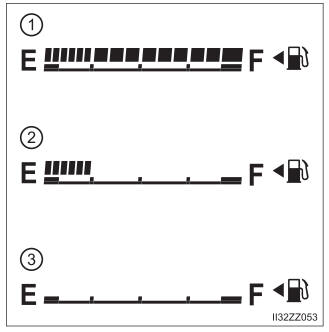
Fuel Gauge
The fuel gauge shows approximately how much fuel is remaining in the tank when the ignition is switched ON. We recommend keeping the tank over 1/4 full.

Copyright © 2026 www.toyaris4.com