Toyota Yaris: Airbag System / System Diagram
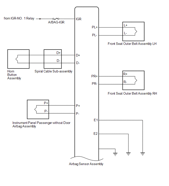
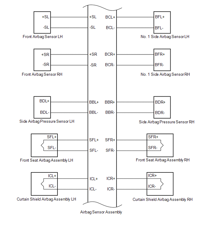
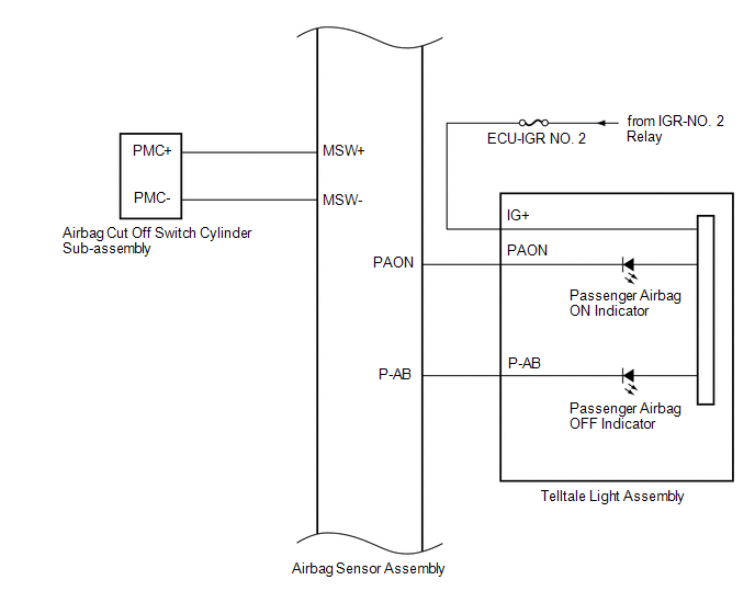
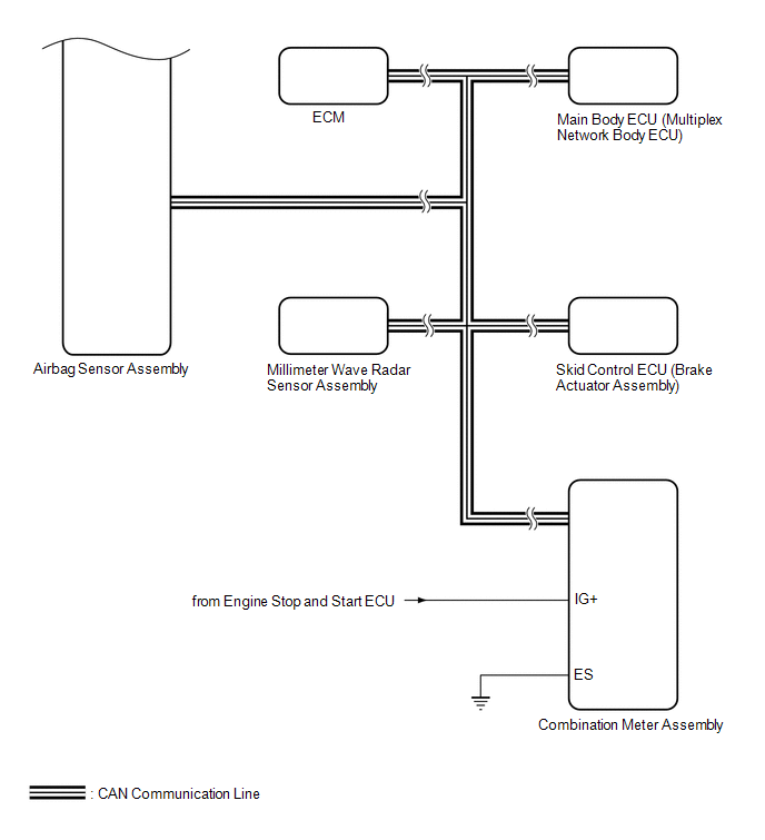
SYSTEM DIAGRAM
 Communication Table
 | Transmitting ECU / Parts (Transmitter) | Receiving ECU / Parts (Receiver) | Signal | Communication Method |
|---|---|---|---|
| Front Airbag Sensor | Airbag Sensor Assembly |
| Direct line |
| No. 1 Side Airbag Sensor |
| ||
| Side Airbag Pressure Sensor |
| ||
| Airbag Cut Off Switch Cylinder Sub-assembly |
| ||
| Airbag Sensor Assembly | Horn Button Assembly |
| |
| Instrument Panel Passenger without Door Airbag Assembly | |||
| Front Seat Airbag Assembly | |||
| Curtain Shield Airbag Assembly | |||
| Front Seat Outer Belt Assembly | |||
| Passenger Airbag ON/OFF Indicator (Telltale Light Assembly) |
| ||
| ECM |
| CAN | |
| Skid Control ECU (Brake Actuator Assembly) |
| ||
| Combination Meter Assembly |
| ||
| Main Body ECU (Multiplex Network Body ECU) |
| ||
| Millimeter Wave Radar Sensor Assembly | Airbag Sensor Assembly |
|
 Parts Location
PARTS LOCATION ILLUSTRATION
*1 FRONT AIRBAG SENSOR LH *2 FRONT AIRBAG SENSOR RH *3 SIDE AIRBAG PRESSURE SENSOR LH *4 SIDE AIRBAG PRESSURE SENSOR RH *5 NO...
 System Description
SYSTEM DESCRIPTION FUNCTION OF SRS CONNECTORS (a) Location of activation prevention mechanism
(b) Function of activation prevention mechanism
(1) This mechanism is designed to create a short circuit automatically between the positive (+) and negative (-) terminals of a squib power source connector when disconnected...
Other information:
Toyota Yaris XP210 (2020-2026) Reapir and Service Manual: Front Fog Light Circuit
DESCRIPTION The main body ECU (multiplex network body ECU) controls the front fog lights. WIRING DIAGRAM CAUTION / NOTICE / HINT NOTICE: Before replacing the main body ECU (multiplex network body ECU), refer to Registration. Click here First, confirm that there is no malfunction in the power integration system...
Toyota Yaris XP210 (2020-2026) Reapir and Service Manual: Yaw Rate Sensor Circuit Intermittent (C00631F,C05201F)
DESCRIPTION The airbag sensor assembly has a built-in yaw rate and acceleration sensor and detects the vehicle condition. The skid control ECU (brake actuator assembly) receives signals from the yaw rate and acceleration sensor (airbag sensor assembly) via CAN communication...
Categories
- Manuals Home
- Toyota Yaris Owners Manual
- Toyota Yaris Service Manual
- Brake System Control Module "A" System Voltage System Voltage Low (C137BA2)
- Battery Monitor Module General Electrical Failure (P058A01)
- How to connect USB port/Auxiliary jack
- New on site
- Most important about car
Front Seat Belt Pretensioners
The front seat belt pretensioners are designed to deploy in moderate or severe frontal, near frontal collisions.
In addition, the pretensioners operate when a side collision or a rollover accident is detected. The pretensioners operate differently depending on what types of air bags are equipped. For more details about the seat belt pretensioner operation, refer to the SRS Air Bag Deployment Criteria.