Toyota Yaris: Airbag System / System Description
SYSTEM DESCRIPTION
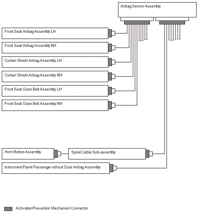
FUNCTION OF SRS CONNECTORS
(a) Location of activation prevention mechanism
(b) Function of activation prevention mechanism
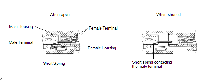
(1) This mechanism is designed to create a short circuit automatically between the positive (+) and negative (-) terminals of a squib power source connector when disconnected.
(2) The short spring contained in the connector creates a closed circuit on the squib side (no potential difference can occur between both terminals), preventing accidental squib deployment when servicing.
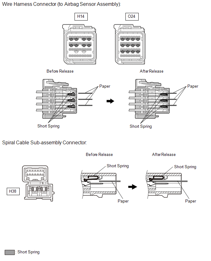
(c) Releasing of activation prevention mechanism
(1) To release the activation prevention mechanism, insert a piece of paper with the same thickness as the male terminal (approximately 0.5 mm (0.0197 in.)) between the terminals and short spring to break the connection.
(2) Refer to the following illustrations concerning connectors utilizing the activation prevention mechanism and its release method.
CAUTION:
Never release the activation prevention mechanism on the squib connector even when inspecting with the squib disconnected.
NOTICE:
- Do not release the activation prevention mechanism unless specified by the troubleshooting procedure.
- To prevent the terminals and short spring from being damaged, always use a piece of paper with the same thickness as the male terminal.
HINT:
To prevent improper operation due to static electricity, etc., the connector of the SRS airbag squib circuit has a short mechanism, and the airbag terminal is shorted while the connector is disconnected.
 System Diagram
SYSTEM DIAGRAM
Communication Table Transmitting ECU / Parts (Transmitter) Receiving ECU / Parts (Receiver) Signal Communication Method Front Airbag Sensor Airbag Sensor Assembly
Front collision G signal
Direct line No...
 How To Proceed With Troubleshooting
CAUTION / NOTICE / HINT HINT:
Use the following procedure to troubleshoot the airbag system.
*: Use the GTS.
PROCEDURE 1. VEHICLE BROUGHT TO WORKSHOP
NEXT
2...
Other information:
Toyota Yaris XP210 (2020-2026) Reapir and Service Manual: ABS Pump Motor Actuator Stuck (C142771)
DESCRIPTION DTC No. Detection Item DTC Detection Condition Trouble Area DTC Output from C142771 ABS Pump Motor Actuator Stuck Actuator pump motor does not operate properly. Wire harness and connector Brake actuator assembly (Pump motor) Brake actuator assembly (Pump motor circuit) Brake WIRING DIAGRAM Refer to DTC C052C13...
Toyota Yaris XP210 (2020-2026) Owner's Manual: Operating Tips
Operate the climate control system with the engine running. To prevent the battery from being discharged, do not leave the fan control dial on for a long period of time with the ignition switched ON when the engine is not running. Clear all obstructions such as leaves, snow and ice from the hood and the air inlet in the cowl grille to improve the system efficiency...
Categories
- Manuals Home
- Toyota Yaris Owners Manual
- Toyota Yaris Service Manual
- How to use USB mode
- To Set Speed
- How to connect USB port/Auxiliary jack
- New on site
- Most important about car
Keys

To use the auxiliary key, press the knob and pull out the auxiliary key from the smart key.
