Toyota Yaris: Sfi System / Crankshaft Position Sensor "A" Circuit Intermittent (P03351F,P03352A,P033531)
DESCRIPTION
Refer to DTC P033511.
Click here

| DTC No. | Detection Item | DTC Detection Condition | Trouble Area | MIL | Note |
|---|---|---|---|---|---|
| P03351F | Crankshaft Position Sensor "A" Circuit Intermittent | Under conditions (a), (b) and (c), no crankshaft position sensor signal to ECM for 0.05 seconds or more (1 trip detection logic): (a) Engine speed is 1000 rpm or higher. (b) Starter signal is off. (c) 3 seconds or more have elapsed since the starter signal switched from on to off. * |
| - | SAE: P0339 |
| P03352A | Crankshaft Position Sensor "A" Signal Stuck in Range | No crankshaft position sensor signal to the ECM while cranking (1 trip detection logic). * |
| Comes on | SAE: P0335 |
| P033531 | Crankshaft Position Sensor "A" No Signal | The engine stalls and the engine speed signal value decreases rapidly (1 trip detection logic). * |
| Comes on | SAE: P0335 |
*: When the engine is being stopped or started automatically by stop and start system control, the ECM does not monitor the crankshaft position sensor signal.
-
Reference: Inspection using an oscilloscope.
Click here

MONITOR DESCRIPTION
A DTC will be stored if any of the following occurs:
- The crankshaft position sensor signal (NE signal) is not received by the ECM when the engine is being cranked.
- The crankshaft position sensor signal (NE signal) is not received by the ECM when the engine is running.
- The engine stalls and the engine speed signal value decreases rapidly (under normal conditions the engine speed will decrease gradually).
MONITOR STRATEGY
| Required Sensors/Components (Main) | Crankshaft position sensor |
| Required Sensors/Components (Related) | Camshaft position sensor |
| Frequency of Operation | Continuous |
CONFIRMATION DRIVING PATTERN
- Connect the GTS to the DLC3.
- Turn the ignition switch to ON.
- Turn the GTS on.
- Clear the DTCs (even if no DTCs are stored, perform the clear DTC procedure).
- Turn the ignition switch off and wait for at least 30 seconds.
- Start the engine.
- Idle the engine for 20 seconds or more [A].
- Run the engine at an engine speed of 1000 rpm for 5 seconds or more [B].
- Turn the GTS on.
- Enter the following menus: Powertrain / Engine / Trouble Codes [C].
-
Read the pending DTCs.
HINT:
- If a pending DTC is output, the system is malfunctioning.
- If a pending DTC is not output, perform the following procedure.
- Enter the following menus: Powertrain / Engine / Utility / All Readiness.
- Input the DTC: P03351F, P03352A or P033531.
-
Check the DTC judgment result.
GTS Display
Description
NORMAL
- DTC judgment completed
- System normal
ABNORMAL
- DTC judgment completed
- System abnormal
INCOMPLETE
- DTC judgment not completed
- Perform driving pattern after confirming DTC enabling conditions
HINT:
- If the judgment result is NORMAL, the system is normal.
- If the judgment result is ABNORMAL, the system has a malfunction.
- If the judgment result is INCOMPLETE, perform steps [A] through [C] again.
WIRING DIAGRAM
Refer to DTC P033511.
Click here

CAUTION / NOTICE / HINT
HINT:
- If no problem is found by this diagnostic troubleshooting procedure, check for problems by referring to the engine mechanical section.
-
The engine speed can be checked by using the GTS. To perform the check, follow the procedures below:
- Connect the GTS to the DLC3.
- Turn the ignition switch to ON.
- Turn the GTS on.
- Enter the following menus: Powertrain / Engine / Data List / Engine Speed.
- Start the engine.
- The engine speed may be indicated as zero despite the engine running normally. This is caused by a lack of NE signals from the crankshaft position sensor. Alternatively, the engine speed may be indicated as lower than the actual engine speed if the crankshaft position sensor output voltage is insufficient.
- Read Freeze Frame Data using the GTS. The ECM records vehicle and driving condition information as Freeze Frame Data the moment a DTC is stored. When troubleshooting, Freeze Frame Data can help determine if the vehicle was moving or stationary, if the engine was warmed up or not, if the air fuel ratio was lean or rich, and other data from the time the malfunction occurred.
PROCEDURE
| 1. | READ VALUE USING GTS (ENGINE SPEED) |
(a) Enter the following menus.
Powertrain > Engine > Data List| Tester Display |
|---|
| Engine Speed |
(b) Start the engine.
(c) Read the values displayed on the GTS while the engine is running.
Standard:
Correct values are displayed.
HINT:
- To check the engine speed change, display the graph on the GTS.
- If the engine does not start, check the engine speed while cranking.
- If the engine speed indicated on the GTS remains at zero (0), there may be an open or short in the crankshaft position sensor circuit.
| OK |
 | CHECK FOR INTERMITTENT PROBLEMS |
|

| 2. | CHECK HARNESS AND CONNECTOR |
HINT:
Make sure that the connector is properly connected. If it is not, securely connect it and check for DTCs again.
(a) Disconnect the crankshaft position sensor connector.
(b) Turn the ignition switch to ON.
| (c) Measure the voltage according to the value(s) in the table below. Standard Voltage:
|
|
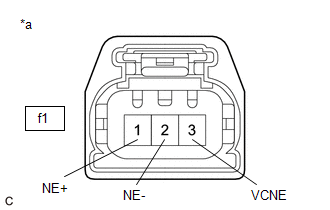
(d) Turn the ignition switch off and wait for at least 30 seconds.
(e) Measure the resistance according to the value(s) in the table below.
Standard Resistance:
| Tester Connection | Condition | Specified Condition |
|---|---|---|
| f1-3(VCNE) - f1-1(NE+) | Ignition switch off | 1.425 to 1.575 kΩ |
| f1-2(NE-) - Body ground | Always | Below 1 Ω |
| NG |
 | GO TO STEP 5 |
|

| 3. | CHECK SENSOR INSTALLATION AND CONDUCT VISUAL INSPECTION (CRANKSHAFT POSITION SENSOR) |

| *a | Clearance |
(a) Visually check the crankshaft position sensor for damage.
(b) Check the crankshaft position sensor installation condition.
OK:
The crankshaft position sensor does not have any damage and is installed properly.
| NG |
 | SECURELY REINSTALL CRANKSHAFT POSITION SENSOR |
|

| 4. | INSPECT CRANKSHAFT POSITION SENSOR PLATE (TEETH OF CRANKSHAFT POSITION SENSOR PLATE) |
(a) Inspect the teeth of the crankshaft position sensor plate.
OK:
Crankshaft position sensor plate does not have any cracks or deformation.
| OK |
 | REPLACE CRANKSHAFT POSITION SENSOR |
| NG |
 | REPLACE CRANKSHAFT POSITION SENSOR PLATE |
| 5. | CHECK HARNESS AND CONNECTOR (CRANKSHAFT POSITION SENSOR - ECM) |
(a) Disconnect the crankshaft position sensor connector.
(b) Disconnect the ECM connector.
(c) Measure the resistance according to the value(s) in the table below.
Standard Resistance:
| Tester Connection | Condition | Specified Condition |
|---|---|---|
| f1-3(VCNE) - D104-116(VCNE) | Always | Below 1 Ω |
| f1-1(NE+) - D104-92(NE+) | Always | Below 1 Ω |
| f1-2(NE-) - D104-115(NE-) | Always | Below 1 Ω |
| f1-3(VCNE) or D104-116(VCNE) - Body ground and other terminals | Always | 10 kΩ or higher |
| f1-1(NE+) or D104-92(NE+) - Body ground and other terminals | Always | 10 kΩ or higher |
| f1-2(NE-) - D104-115(NE-) - Body ground and other terminals | Always | 10 kΩ or higher |
| OK |
 | REPLACE ECM |
| NG |
 | REPAIR OR REPLACE HARNESS OR CONNECTOR |
 Crankshaft Position Sensor "A" Circuit Short to Ground (P033511,P033515)
DESCRIPTION The crankshaft position sensor system consists of a crankshaft position sensor plate and Magneto-Resistive Element (MRE) type sensor. The crankshaft position sensor plate has 34 teeth at 10° intervals (2 teeth are missing for detecting top dead center), and is installed on the crankshaft...
 Camshaft Position Sensor "A" Bank 1 or Single Sensor No Signal (sub) (P034000)
DESCRIPTION Refer to DTC P034011. Click here
DTC No. Detection Item DTC Detection Condition Trouble Area MIL Note P034000 Camshaft Position Sensor "A" Bank 1 or Single Sensor No Signal (sub) No camshaft position sensor (for intake camshaft) signal to the sub ECM while engine running ECM Comes on SAE: P0340 MONITOR DESCRIPTION While the engine is running, when the VV1 (VV2) signal is not input to the sub CPU even though the VV1 (VV2) signal is input to the main CPU, the ECM judges that a malfunction has occurred in an internal ECM circuit, and illuminates the MIL and stores a DTC...
Other information:
Toyota Yaris XP210 (2020-2026) Reapir and Service Manual: Power Steering Torque Sensor "A" Supply Voltage Circuit Voltage Above Threshold (C151A17)
DESCRIPTION The power steering ECU assembly supplies a voltage of 5 V to the torque sensor (electric power steering column sub-assembly) and monitors the voltage value of the Hall IC inside the torque sensor (electric power steering column sub-assembly) which changes in response to changes in the magnetic flux density (steering torque) detected by the Hall IC, and calculates the assist torque...
Toyota Yaris XP210 (2020-2026) Reapir and Service Manual: Components
COMPONENTS ILLUSTRATION *1 OUTPUT SHAFT BEARING SHAFT SNAP RING *2 NEEDLE ROLLER BEARING *3 SYNCHRONIZER SHIFTING KEY SPRING *4 SHAFT SNAP RING *5 SPACER *6 BALL *7 OUTPUT SHAFT FRONT BEARING INNER RACE *8 SYNCHROMESH SHIFTING KEY BALL *9 NO...
Categories
- Manuals Home
- Toyota Yaris Owners Manual
- Toyota Yaris Service Manual
- Diagnostic Trouble Code Chart
- How to use USB mode
- Maintenance
- New on site
- Most important about car
Supplemental Restraint System (SRS) Precautions
The front and side supplemental restraint systems (SRS) include different types of air bags. Please verify the different types of air bags which are equipped on your vehicle by locating the “SRS AIRBAG” location indicators. These indicators are visible in the area where the air bags are installed.
The air bags are installed in the following locations:
The steering wheel hub (driver air bag) The front passenger dashboard (front passenger air bag) The outboard sides of the front seatbacks (side air bags) The front and rear window pillars, and the roof edge along both sides (curtain air bags)