Toyota Yaris: Sfi System / Crankshaft Position Sensor "A" Circuit Short to Ground (P033511,P033515)
DESCRIPTION
The crankshaft position sensor system consists of a crankshaft position sensor plate and Magneto-Resistive Element (MRE) type sensor. The crankshaft position sensor plate has 34 teeth at 10° intervals (2 teeth are missing for detecting top dead center), and is installed on the crankshaft. The crankshaft position sensor generates 34 signals per crankshaft revolution. The ECM uses the crankshaft position sensor signal (NE signal) to detect the crankshaft position and engine speed.
| DTC No. | Detection Item | DTC Detection Condition | Trouble Area | MIL | Note |
|---|---|---|---|---|---|
| P033511 | Crankshaft Position Sensor "A" Circuit Short to Ground | The crankshaft position sensor output voltage is less than 0.3 V for 4 seconds or more (1 trip detection logic). |
| Comes on | SAE: P0337 |
| P033515 | Crankshaft Position Sensor "A" Circuit Short to Battery or Open | The crankshaft position sensor output voltage is higher than 4.7 V for 4 seconds or more (1 trip detection logic). |
| Comes on | SAE: P0338 |
-
Reference: Inspection using an oscilloscope.
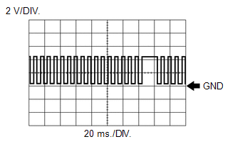
HINT:
The correct waveform is as shown.
ECM Terminal Name
Between NE+ and NE-
Tester Range
2 V/DIV., 20 ms./DIV.
Condition
Idling with warm engine
MONITOR DESCRIPTION
If the output voltage transmitted by the crankshaft position sensor remains low or high, the ECM interprets this as a malfunction in the sensor circuit, illuminates the MIL and stores a DTC.
MONITOR STRATEGY
| Required Sensors/Components (Main) | Crankshaft position sensor |
| Required Sensors/Components (Related) | Camshaft position sensor |
| Frequency of Operation | Continuous |
CONFIRMATION DRIVING PATTERN
- Connect the GTS to the DLC3.
- Turn the ignition switch to ON.
- Turn the GTS on.
- Clear the DTCs (even if no DTCs are stored, perform the clear DTC procedure).
- Turn the ignition switch off and wait for at least 30 seconds.
- Turn the ignition switch to ON.
- Turn the GTS on.
- Start the engine.
- Idle the engine for 20 seconds or more.
- Enter the following menus: Powertrain / Engine / Trouble Codes.
-
Read the pending DTCs.
HINT:
- If a pending DTC is output, the system is malfunctioning.
- If a pending DTC is not output, perform the following procedure.
- Enter the following menus: Powertrain / Engine / Utility / All Readiness.
- Input the DTC: P033511 or P033515.
-
Check the DTC judgment result.
GTS Display
Description
NORMAL
- DTC judgment completed
- System normal
ABNORMAL
- DTC judgment completed
- System abnormal
INCOMPLETE
- DTC judgment not completed
- Perform driving pattern after confirming DTC enabling conditions
HINT:
- If the judgment result is NORMAL, the system is normal.
- If the judgment result is ABNORMAL, the system has a malfunction.
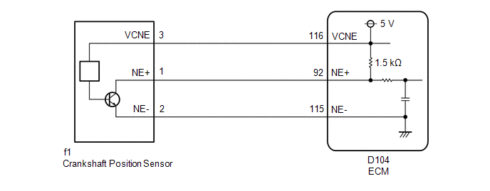
WIRING DIAGRAM
CAUTION / NOTICE / HINT
HINT:
-
The engine speed can be checked by using the GTS. To perform the check, follow the procedures below:
- Connect the GTS to the DLC3.
- Turn the ignition switch to ON.
- Turn the GTS on.
- Enter the following menus: Powertrain / Engine / Data List / Engine Speed.
- Start the engine.
- The engine speed may be indicated as zero despite the engine running normally. This is caused by a lack of NE signals from the crankshaft position sensor. Alternatively, the engine speed may be indicated as lower than the actual engine speed if the crankshaft position sensor output voltage is insufficient.
- Read Freeze Frame Data using the GTS. The ECM records vehicle and driving condition information as Freeze Frame Data the moment a DTC is stored. When troubleshooting, Freeze Frame Data can help determine if the vehicle was moving or stationary, if the engine was warmed up or not, if the air fuel ratio was lean or rich, and other data from the time the malfunction occurred.
PROCEDURE
| 1. | READ VALUE USING GTS (ENGINE SPEED) |
(a) Enter the following menus.
Powertrain > Engine > Data List| Tester Display |
|---|
| Engine Speed |
(b) Start the engine.
(c) Read the values displayed on the GTS while the engine is running.
Standard:
Correct values are displayed.
HINT:
- To check the engine speed change, display the graph on the GTS.
- If the engine does not start, check the engine speed while cranking.
- If the engine speed indicated on the GTS remains at zero (0), there may be an open or short in the crankshaft position sensor circuit.
| OK |
 | CHECK FOR INTERMITTENT PROBLEMS |
|

| 2. | CHECK HARNESS AND CONNECTOR |
HINT:
Make sure that the connector is properly connected. If it is not, securely connect it and check for DTCs again.
(a) Disconnect the crankshaft position sensor connector.
(b) Turn the ignition switch to ON.
| (c) Measure the voltage according to the value(s) in the table below. Standard Voltage:
|
|
(d) Turn the ignition switch off and wait for at least 30 seconds.
(e) Measure the resistance according to the value(s) in the table below.
Standard Resistance:
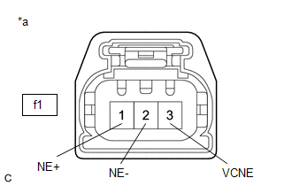
| Tester Connection | Condition | Specified Condition |
|---|---|---|
| f1-3(VCNE) - f1-1(NE+) | Ignition switch off | 1.425 to 1.575 kΩ |
| f1-2(NE-) - Body ground | Always | Below 1 Ω |
| OK |
 | REPLACE CRANKSHAFT POSITION SENSOR |
|

| 3. | CHECK HARNESS AND CONNECTOR (CRANKSHAFT POSITION SENSOR - ECM) |
(a) Disconnect the crankshaft position sensor connector.
(b) Disconnect the ECM connector.
(c) Measure the resistance according to the value(s) in the table below.
Standard Resistance:
| Tester Connection | Condition | Specified Condition |
|---|---|---|
| f1-3(VCNE) - D104-116(VCNE) | Always | Below 1 Ω |
| f1-1(NE+) - D104-92(NE+) | Always | Below 1 Ω |
| f1-2(NE-) - D104-115(NE-) | Always | Below 1 Ω |
| f1-3(VCNE) or D104-116(VCNE) - Body ground and other terminals | Always | 10 kΩ or higher |
| f1-1(NE+) or D104-92(NE+) - Body ground and other terminals | Always | 10 kΩ or higher |
| f1-2(NE-) or D104-115(NE-) - Body ground and other terminals | Always | 10 kΩ or higher |
| OK |
 | REPLACE ECM |
| NG |
 | REPAIR OR REPLACE HARNESS OR CONNECTOR |
 Crankshaft Position Sensor "A" No Signal (sub) (P033500)
DESCRIPTION Refer to DTC P033511. Click here
DTC No. Detection Item DTC Detection Condition Trouble Area MIL Note P033500 Crankshaft Position Sensor "A" No Signal (sub) No crankshaft position sensor signal to the sub ECM while engine running ECM Comes on SAE: P0335 MONITOR DESCRIPTION While the engine is running, when the NE signal is not input to the sub CPU even though the NE signal is input to the main CPU, the ECM judges that a malfunction has occurred in an internal ECM circuit, and illuminates the MIL and stores a DTC...
 Crankshaft Position Sensor "A" Circuit Intermittent (P03351F,P03352A,P033531)
DESCRIPTION Refer to DTC P033511. Click here
DTC No. Detection Item DTC Detection Condition Trouble Area MIL Note P03351F Crankshaft Position Sensor "A" Circuit Intermittent Under conditions (a), (b) and (c), no crankshaft position sensor signal to ECM for 0...
Other information:
Toyota Yaris XP210 (2020-2025) Reapir and Service Manual: Throttle / Pedal Position Sensor / Switch "A" Circuit Short to Ground (P012011)
DESCRIPTION The throttle position sensor is built into the throttle body with motor assembly and detects the opening angle of the throttle valve. This sensor is a non-contact type sensor. It uses Hall-effect elements in order to yield accurate signals even in extreme driving conditions, such as at high speeds as well as very low speeds...
Toyota Yaris XP210 (2020-2025) Reapir and Service Manual: Back Door Entry Lock Function does not Operate
DESCRIPTION If the entry lock function does not operate for the back door only, but the entry unlock function operates, the request code is being transmitted properly from the back door. In this case, there may be a problem related to the lock switch (connection between the back door opener switch assembly and certification ECU (smart key ECU assembly))...
Categories
- Manuals Home
- Toyota Yaris Owners Manual
- Toyota Yaris Service Manual
- Maintenance
- Removal
- Brake System Control Module "A" System Voltage System Voltage Low (C137BA2)
- New on site
- Most important about car
Break-In Period
No special break-in is necessary, but a few precautions in the first 600 miles (1,000 km) may add to the performance, economy, and life of the vehicle.
Do not race the engine. Do not maintain one constant speed, either slow or fast, for a long period of time. Do not drive constantly at full-throttle or high engine rpm for extended periods of time. Avoid unnecessary hard stops. Avoid full-throttle starts.