Toyota Yaris: Sfi System / Crankshaft Position Sensor "A" No Signal (sub) (P033500)
DESCRIPTION
Refer to DTC P033511.
Click here

| DTC No. | Detection Item | DTC Detection Condition | Trouble Area | MIL | Note |
|---|---|---|---|---|---|
| P033500 | Crankshaft Position Sensor "A" No Signal (sub) | No crankshaft position sensor signal to the sub ECM while engine running | ECM | Comes on | SAE: P0335 |
MONITOR DESCRIPTION
While the engine is running, when the NE signal is not input to the sub CPU even though the NE signal is input to the main CPU, the ECM judges that a malfunction has occurred in an internal ECM circuit, and illuminates the MIL and stores a DTC.
MONITOR STRATEGY
| Required Sensors/Components (Main) | Crankshaft position sensor |
| Required Sensors/Components (Related) | Camshaft position sensor |
| Frequency of Operation | Continuous |
CONFIRMATION DRIVING PATTERN
- Connect the GTS to the DLC3.
- Turn the ignition switch to ON.
- Turn the GTS on.
- Clear the DTCs (even if no DTCs are stored, perform the clear DTC procedure).
- Turn the ignition switch off and wait for at least 30 seconds.
- Turn the ignition switch to ON.
- Turn the GTS on.
- Start the engine.
- Idle the engine for 20 seconds or more.
- Enter the following menus: Powertrain / Engine / Trouble Codes.
-
Read the pending DTCs.
HINT:
- If a pending DTC is output, the system is malfunctioning.
- If a pending DTC is not output, perform the following procedure.
- Enter the following menus: Powertrain / Engine / Utility / All Readiness.
- Input the DTC: P033500.
-
Check the DTC judgment result.
GTS Display
Description
NORMAL
- DTC judgment completed
- System normal
ABNORMAL
- DTC judgment completed
- System abnormal
INCOMPLETE
- DTC judgment not completed
- Perform driving pattern after confirming DTC enabling conditions
HINT:
- If the judgment result is NORMAL, the system is normal.
- If the judgment result is ABNORMAL, the system has a malfunction.
CAUTION / NOTICE / HINT
HINT:
Read Freeze Frame Data using the GTS. The ECM records vehicle and driving condition information as Freeze Frame Data the moment a DTC is stored. When troubleshooting, Freeze Frame Data can help determine if the vehicle was moving or stationary, if the engine was warmed up or not, if the air fuel ratio was lean or rich, and other data from the time the malfunction occurred.
PROCEDURE
| 1. | CHECK ANY OTHER DTCS OUTPUT (IN ADDITION TO DTC P033500) |
(a) Read the DTCs.
Powertrain > Engine > Trouble Codes| Result | Proceed to |
|---|---|
| P033500 is output | A |
| P033500 and other DTCs are output | B |
HINT:
If any DTCs other than P033500 are output, troubleshoot those DTCs first.
| A |
 | REPLACE ECM |
| B |
 | GO TO DTC CHART |
 Knock Sensor 1 Bank 1 or Single Sensor Circuit Short to Battery or Open (P032515)
DESCRIPTION Refer to DTC P032511. Click here
HINT: When DTC P032515 is stored, the ECM enters fail-safe mode. During fail-safe mode, the ignition timing is delayed to its maximum retardation...
 Crankshaft Position Sensor "A" Circuit Short to Ground (P033511,P033515)
DESCRIPTION The crankshaft position sensor system consists of a crankshaft position sensor plate and Magneto-Resistive Element (MRE) type sensor. The crankshaft position sensor plate has 34 teeth at 10° intervals (2 teeth are missing for detecting top dead center), and is installed on the crankshaft...
Other information:
Toyota Yaris XP210 (2020-2026) Owner's Manual: Windshield Defrosting and Defogging
Set the mode selector dial to the position and turn the fan control dial to the desired speed. In this position, the outside air position is automatically selected, and when the fan control dial is ON, the air conditioner automatically turns on...
Toyota Yaris XP210 (2020-2026) Reapir and Service Manual: G16e-gts Air Cleaner Filter Element
ComponentsCOMPONENTS ILLUSTRATION *1 AIR CLEANER CAP SUB-ASSEMBLY *2 AIR CLEANER FILTER ELEMENT SUB-ASSEMBLY RemovalREMOVAL PROCEDURE 1. SEPARATE AIR CLEANER CAP SUB-ASSEMBLY (a) Disconnect the 2 clamp hooks from the air cleaner cap sub-assembly...
Categories
- Manuals Home
- Toyota Yaris Owners Manual
- Toyota Yaris Service Manual
- Removal
- Immobilizer System
- To Set Speed
- New on site
- Most important about car
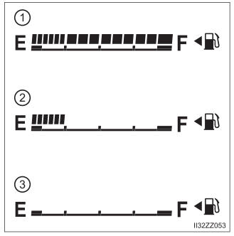
Fuel Gauge
The fuel gauge shows approximately how much fuel is remaining in the tank when the ignition is switched ON. We recommend keeping the tank over 1/4 full.