Toyota Yaris: Sfi System / Knock Sensor 1 Bank 1 or Single Sensor Circuit Short to Battery or Open (P032515)
DESCRIPTION
Refer to DTC P032511.
Click here

HINT:
When DTC P032515 is stored, the ECM enters fail-safe mode. During fail-safe mode, the ignition timing is delayed to its maximum retardation. Fail-safe mode continues until the ignition switch is turned off.
| DTC No. | Detection Item | DTC Detection Condition | Trouble Area | MIL | Note |
|---|---|---|---|---|---|
| P032515 | Knock Sensor 1 Bank 1 or Single Sensor Circuit Short to Battery or Open | The knock control sensor output voltage is higher than 4.5 V for 1 second or more (1 trip detection logic). |
| Comes on | SAE: P0328 |
Reference: Inspection using an oscilloscope.
Click here

MONITOR DESCRIPTION
If the output voltage transmitted by the knock control sensor remains high for 1 second or more, the ECM interprets this as a malfunction in the sensor circuit, illuminates the MIL and stores this DTC.
MONITOR STRATEGY
| Frequency of Operation | Continuous |
CONFIRMATION DRIVING PATTERN
- Connect the GTS to the DLC3.
- Turn the ignition switch to ON.
- Turn the GTS on.
- Clear the DTCs (even if no DTCs are stored, perform the clear DTC procedure).
- Turn the ignition switch off and wait for at least 30 seconds.
- Start the engine and wait 5 minutes.
- Turn the GTS on.
- Enter the following menus: Powertrain / Engine / Trouble Codes.
-
Read the pending DTCs.
HINT:
- If a pending DTC is output, the system is malfunctioning.
- If a pending DTC is not output, perform the following procedure.
- Enter the following menus: Powertrain / Engine / Utility / All Readiness.
- Input the DTC: P032515
-
Check the DTC judgment result.
GTS Display
Description
NORMAL
- DTC judgment completed
- System normal
ABNORMAL
- DTC judgment completed
- System abnormal
INCOMPLETE
- DTC judgment not completed
- Perform driving pattern after confirming DTC enabling conditions
HINT:
- If the judgment result is NORMAL, the system is normal.
- If the judgment result is ABNORMAL, the system is malfunctioning.
- If the judgment result is INCOMPLETE, idle the engine for 5 minutes and check the DTC judgment result again.
WIRING DIAGRAM
Refer to DTC P032511.
Click here

CAUTION / NOTICE / HINT
HINT:
Read Freeze Frame Data using the GTS. The ECM records vehicle and driving condition information as Freeze Frame Data the moment a DTC is stored. When troubleshooting, Freeze Frame Data can help determine if the vehicle was moving or stationary, if the engine was warmed up or not, if the air fuel ratio was lean or rich, and other data from the time the malfunction occurred.
PROCEDURE
| 1. | CHECK TERMINAL VOLTAGE (POWER SOURCE OF KNOCK CONTROL SENSOR) |
(a) Disconnect the knock control sensor connector.
(b) Turn the ignition switch to ON.
| (c) Measure the voltage according to the value(s) in the table below. Standard Voltage:
|
|
| NG |
 | GO TO STEP 3 |
|

| 2. | INSPECT KNOCK CONTROL SENSOR |
Click here

HINT:
Perform "Inspection After Repair" after replacing the knock control sensor.
Click here

| OK |
 | GO TO STEP 4 |
| NG |
 | REPLACE KNOCK CONTROL SENSOR |
| 3. | CHECK HARNESS AND CONNECTOR (KNOCK CONTROL SENSOR - ECM) |
(a) Disconnect the knock control sensor connector.
(b) Disconnect the ECM connector.
(c) Measure the resistance according to the value(s) in the table below.
Standard Resistance:
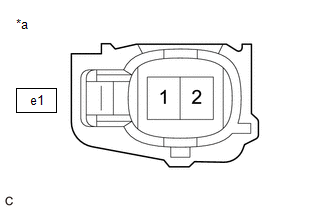
| Tester Connection | Condition | Specified Condition |
|---|---|---|
| e1-2(KNK1) - D104-111(KNK1) | Always | Below 1 Ω |
| e1-1(EKNK) - D104-112(EKNK) | Always | Below 1 Ω |
| e1-2(KNK1) or D104-111(KNK1) - Other terminals | Always | 10 kΩ or higher |
| NG |
 | REPAIR OR REPLACE HARNESS OR CONNECTOR |
|

| 4. | CLEAR DTC |
(a) Clear the DTCs.
Powertrain > Engine > Clear DTCs(b) Turn the ignition switch off and wait for at least 30 seconds.
|

| 5. | CHECK WHETHER DTC OUTPUT RECURS (DTC P032515) |
(a) Drive the vehicle in accordance with the driving pattern described in Confirmation Driving Pattern.
(b) Read the DTCs.
Powertrain > Engine > Trouble Codes| Result | Proceed to |
|---|---|
| DTCs are not output | A |
| P032515 is output | B |
| A |
 | CHECK FOR INTERMITTENT PROBLEMS |
| B |
 | REPLACE ECM |
 Knock Sensor 1 Bank 1 or Single Sensor Circuit Short to Ground (P032511)
DESCRIPTION A flat-type knock control sensor (non-resonant type) has a structure that can detect vibrations between approximately 5 and 23 kHz. The knock control sensor is fitted onto the engine block to detect engine knocking...
 Crankshaft Position Sensor "A" No Signal (sub) (P033500)
DESCRIPTION Refer to DTC P033511. Click here
DTC No. Detection Item DTC Detection Condition Trouble Area MIL Note P033500 Crankshaft Position Sensor "A" No Signal (sub) No crankshaft position sensor signal to the sub ECM while engine running ECM Comes on SAE: P0335 MONITOR DESCRIPTION While the engine is running, when the NE signal is not input to the sub CPU even though the NE signal is input to the main CPU, the ECM judges that a malfunction has occurred in an internal ECM circuit, and illuminates the MIL and stores a DTC...
Other information:
Toyota Yaris XP210 (2020-2026) Owner's Manual: Towing
Trailer Towing Your Toyota is not designed for towing. Never tow a trailer with your Toyota. Recreational Towing An example of “recreational towing” is towing your vehicle behind a motorhome. The transaxle is not designed for towing this vehicle on all 4 wheels...
Toyota Yaris XP210 (2020-2026) Reapir and Service Manual: Dtc Check / Clear
DTC CHECK / CLEAR CHECK DTC (a) Check for DTCs (Test Failed / Pending / Confirmed). Body Electrical > Pre-Collision System > Trouble Codes GTS Display Description Test Failed Represent malfunctions that were detected during the current trip...
Categories
- Manuals Home
- Toyota Yaris Owners Manual
- Toyota Yaris Service Manual
- Fuse Panel Description
- Engine Start Function When Key Battery is Dead
- Opening and Closing the Liftgate/Trunk Lid
- New on site
- Most important about car
Fuel-Filler Lid and Cap
WARNING
When removing the fuel-filler cap, loosen the cap slightly and wait for any hissing to stop, then remove it
Fuel spray is dangerous. Fuel can burn skin and eyes and cause illness if ingested. Fuel spray is released when there is pressure in the fuel tank and the fuel-filler cap is removed too quickly.