Toyota Yaris: Sfi System / Knock Sensor 1 Bank 1 or Single Sensor Circuit Short to Ground (P032511)
DESCRIPTION
A flat-type knock control sensor (non-resonant type) has a structure that can detect vibrations between approximately 5 and 23 kHz.
The knock control sensor is fitted onto the engine block to detect engine knocking.
The knock control sensor contains a piezoelectric element which generates a voltage when it becomes deformed.
The voltage is generated when the engine block vibrates due to knocking. Any occurrence of engine knocking can be suppressed by delaying the ignition timing.
HINT:
When DTC P032511 is stored, the ECM enters fail-safe mode. During fail-safe mode, the ignition timing is delayed to its maximum retardation. Fail-safe mode continues until the ignition switch is turned off.
| DTC No. | Detection Item | DTC Detection Condition | Trouble Area | MIL | Note |
|---|---|---|---|---|---|
| P032511 | Knock Sensor 1 Bank 1 or Single Sensor Circuit Short to Ground | The knock control sensor output voltage is less than 0.5 V for 1 second or more (1 trip detection logic). |
| Comes on | SAE: P0327 |
Reference: Inspection using an oscilloscope
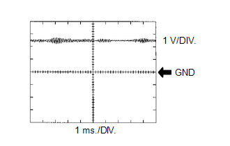
HINT:
The correct waveform is as shown.
| ECM Terminal Name | Between KNK1 and EKNK |
| Tester Range | 1 V/DIV., 1 ms./DIV. |
| Condition | Engine speed maintained at 4000 rpm after warming up the engine |
MONITOR DESCRIPTION
If the output voltage transmitted by the knock control sensor remains low for 1 second or more, the ECM interprets this as a malfunction in the sensor circuit, illuminates the MIL and stores this DTC.
MONITOR STRATEGY
| Frequency of Operation | Continuous |
CONFIRMATION DRIVING PATTERN
- Connect the GTS to the DLC3.
- Turn the ignition switch to ON.
- Turn the GTS on.
- Clear the DTCs (even if no DTCs are stored, perform the clear DTC procedure).
- Turn the ignition switch off and wait for at least 30 seconds.
- Start the engine and wait 5 minutes.
- Turn the GTS on.
- Enter the following menus: Powertrain / Engine / Trouble Codes.
-
Read the pending DTCs.
HINT:
- If a pending DTC is output, the system is malfunctioning.
- If a pending DTC is not output, perform the following procedure.
- Enter the following menus: Powertrain / Engine / Utility / All Readiness.
- Input the DTC: P032511.
-
Check the DTC judgment result.
GTS Display
Description
NORMAL
- DTC judgment completed
- System normal
ABNORMAL
- DTC judgment completed
- System abnormal
INCOMPLETE
- DTC judgment not completed
- Perform driving pattern after confirming DTC enabling conditions
HINT:
- If the judgment result is NORMAL, the system is normal.
- If the judgment result is ABNORMAL, the system is malfunctioning.
- If the judgment result is INCOMPLETE, idle the engine for 5 minutes and check the DTC judgment result again.
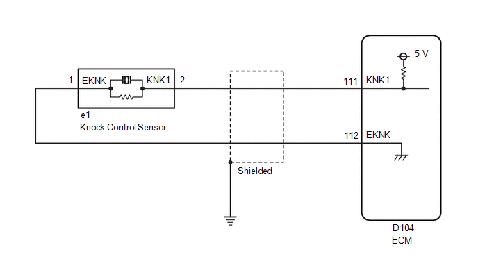
WIRING DIAGRAM
CAUTION / NOTICE / HINT
HINT:
Read Freeze Frame Data using the GTS. The ECM records vehicle and driving condition information as Freeze Frame Data the moment a DTC is stored. When troubleshooting, Freeze Frame Data can help determine if the vehicle was moving or stationary, if the engine was warmed up or not, if the air fuel ratio was lean or rich, and other data from the time the malfunction occurred.
PROCEDURE
| 1. | CHECK TERMINAL VOLTAGE (POWER SOURCE OF KNOCK CONTROL SENSOR) |
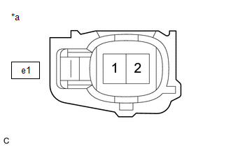
(a) Disconnect the knock control sensor connector.
(b) Turn the ignition switch to ON.
| (c) Measure the voltage according to the value(s) in the table below. Standard Voltage:
|
|
| NG |
 | GO TO STEP 3 |
|

| 2. | INSPECT KNOCK CONTROL SENSOR |
Click here

HINT:
Perform "Inspection After Repair" after replacing the knock control sensor.
Click here

| OK |
 | GO TO STEP 4 |
| NG |
 | REPLACE KNOCK CONTROL SENSOR |
| 3. | CHECK HARNESS AND CONNECTOR (KNOCK CONTROL SENSOR - ECM) |
(a) Disconnect the knock control sensor connector.
(b) Disconnect the ECM connector.
(c) Measure the resistance according to the value(s) in the table below.
Standard Resistance:
| Tester Connection | Condition | Specified Condition |
|---|---|---|
| e1-2(KNK1) or D104-111(KNK1) - Body ground | Always | 10 kΩ or higher |
| NG |
 | REPAIR OR REPLACE HARNESS OR CONNECTOR |
|

| 4. | CLEAR DTC |
(a) Clear the DTCs.
Powertrain > Engine > Clear DTCs(b) Turn the ignition switch off and wait for at least 30 seconds.
|

| 5. | CHECK WHETHER DTC OUTPUT RECURS (DTC P032511) |
(a) Drive the vehicle in accordance with the driving pattern described in Confirmation Driving Pattern.
(b) Read the DTCs.
Powertrain > Engine > Trouble Codes| Result | Proceed to |
|---|---|
| DTCs are not output | A |
| P032511 is output | B |
| A |
 | CHECK FOR INTERMITTENT PROBLEMS |
| B |
 | REPLACE ECM |
 Random/Multiple Cylinder Misfire Detected (P030000,P030027,P030085-P030300)
DESCRIPTION When the engine misfires, high concentrations of hydrocarbons (HC) enter the exhaust gas. Extremely high hydrocarbon concentration levels can cause an increase in exhaust emission levels...
 Knock Sensor 1 Bank 1 or Single Sensor Circuit Short to Battery or Open (P032515)
DESCRIPTION Refer to DTC P032511. Click here
HINT: When DTC P032515 is stored, the ECM enters fail-safe mode. During fail-safe mode, the ignition timing is delayed to its maximum retardation...
Other information:
Toyota Yaris XP210 (2020-2025) Reapir and Service Manual: Replacement
REPLACEMENT CAUTION / NOTICE / HINT The necessary procedures (adjustment, calibration, initialization, or registration) that must be performed after parts are removed and installed, or replaced during the transfer case front oil seal removal/installation are shown below...
Toyota Yaris XP210 (2020-2025) Reapir and Service Manual: Lost Communication with Cruise Control Front Distance Range Sensor Single Sensor or Center Missing Message (U023587)
DESCRIPTION The forward recognition camera and millimeter wave radar sensor assembly communicate via CAN communication. If there is an error in the communication with the millimeter wave radar sensor assembly, the forward recognition camera stores DTC U023587...
Categories
- Manuals Home
- Toyota Yaris Owners Manual
- Toyota Yaris Service Manual
- How to connect USB port/Auxiliary jack
- Battery Monitor Module General Electrical Failure (P058A01)
- Auto Lock/Unlock Function
- New on site
- Most important about car
Key Suspend Function
If a key is left in the vehicle, the functions of the key left in the vehicle are temporarily suspended to prevent theft of the vehicle.
To restore the functions, press the unlock button on the functions-suspended key in the vehicle.