Toyota Yaris: Lane Tracing Assist System / Lost Communication with Cruise Control Front Distance Range Sensor Single Sensor or Center Missing Message (U023587)
DESCRIPTION
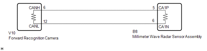
The forward recognition camera and millimeter wave radar sensor assembly communicate via CAN communication. If there is an error in the communication with the millimeter wave radar sensor assembly, the forward recognition camera stores DTC U023587.
| DTC No. | Detection Item | DTC Detection Condition | Trouble Area |
|---|---|---|---|
| U023587 | Lost Communication with Cruise Control Front Distance Range Sensor Single Sensor or Center Missing Message | When the ignition switch is ON for 3 seconds or more, a communication data malfunction between the forward recognition camera and the millimeter wave radar sensor assembly continues for approximately 2 seconds or more. |
|
| Pattern | DTC output part name (Display on GTS) | Suspected Area (Malfunction Status) | |||
|---|---|---|---|---|---|
| Forward Recognition Camera | Millimeter Wave Radar Sensor Assembly | ||||
| Lane Control | Forward Recognition Camera (Front Lighting Control) | Pre-Collision System | Radar Cruise2 | ||
| U023587 | U023587 | U023A87 | U023A87 | ||
|
○: DTC is output
-: DTC is not output | |||||
| Pattern1 | ○ | ○ | ○ | ○ | Harness or connector (Open or short) |
| Forward recognition camera (Internal malfunction) | |||||
| Millimeter wave radar sensor assembly (Internal malfunction) | |||||
| Pattern2 | ○ | ○ | - | - | Forward recognition camera (Internal malfunction) |
| Millimeter wave radar sensor assembly (Internal malfunction) | |||||
HINT:
If the DTCs are output simultaneously, the inspection area can be narrowed down.
WIRING DIAGRAM
CAUTION / NOTICE / HINT
NOTICE:
- When replacing the forward recognition camera, always replace it with a new one. If a forward recognition camera which was installed to another vehicle is used, the information stored in the forward recognition camera will not match the information from the vehicle and a DTC may be stored.
-
When the forward recognition camera is replaced with a new one or the windshield glass is replaced or removed/installed, make sure to read Before Starting Adjustment, then perform optical axis alignment for the forward recognition camera and clear the vehicle control history for each system.
HINT:
Forward recognition camera axis alignment can be performed by using either One Time Recognition, Sequential Recognition or Driving Adjustment.
One Time Recognition: Click here

Sequential Recognition: Click here

Driving Adjustment: Click here

- When replacing the millimeter wave radar sensor assembly, always replace it with a new one. If a millimeter wave radar sensor assembly which was installed to another vehicle is used, the information stored in the millimeter wave radar sensor assembly will not match the information from the vehicle and a DTC may be stored.
-
When the millimeter wave radar sensor assembly has been replaced with a new one, it is necessary to perform millimeter wave radar sensor assembly beam axis alignment and to clear the vehicle control history. Before performing the Driving Adjustment, make sure to read Before Starting Driving Adjustment.
HINT:
Beam axis alignment of the millimeter wave radar sensor assembly can be performed using either Triangle Target, Flat Surface Target or Driving Adjustment.
Triangle Target: Click here

Flat Surface Target: Click here

Driving Adjustment: Click here

-
After the ignition switch is turned off, there may be a waiting time before disconnecting the negative (-) auxiliary battery terminal.
Click here

HINT:
When disconnecting and reconnecting the battery, there is an automatic learning function that completes learning when the respective system is used.
Click here

HINT:
If there are communication malfunctions for systems other than the forward recognition camera and millimeter wave radar sensor assembly, refer to "HOW TO PROCEED WITH TROUBLESHOOTING" for the CAN Communication System.
Click here

PROCEDURE
| 1. | CHECK FOR DTC |
(a) Read each DTC and check the diagnosis pattern using the table below.
Chassis > Lane Control > Trouble Codes Body Electrical > Front Recognition Camera (Front Lighting Control) > Trouble Codes Body Electrical > Pre-Collision System > Trouble Codes Powertrain > Radar Cruise2 > Trouble Codes| Pattern | DTC output part name (Display on GTS / Output DTC) | |||
|---|---|---|---|---|
| Lane Control | Forward Recognition Camera (Front Lighting Control) | Pre-Collision System | Radar Cruise2 | |
| Pattern 1 | U023587 | U023587 | U023A87 | U023A87 |
| Pattern 2 | U023587 | U023587 | - | - |
| Result | Proceed to |
|---|---|
| Pattern 1 | A |
| Pattern 2 | B |
| B |
 | GO TO STEP 4 |
|

| 2. | CHECK CAN MAIN WIRE (FORWARD RECOGNITION CAMERA) |
(a) Disconnect the cable from the negative (-) auxiliary battery terminal.
(b) Disconnect the V10 forward recognition camera connector.
(c) Measure the resistance according to the value(s) in the table below.
Standard Resistance:
| Tester Connection | Condition | Specified Condition |
|---|---|---|
| V10-6 (CANH) - V10-12 (CANL) | Cable disconnected from negative (-) auxiliary battery terminal | 108 to 132 Ω |
| V10-6 (CANH) - Body ground | Cable disconnected from negative (-) auxiliary battery terminal | 200 Ω or higher |
| V10-12 (CANL) - Body ground | Cable disconnected from negative (-) auxiliary battery terminal | 200 Ω or higher |
| V10-6 (CANH) - +B | Cable disconnected from negative (-) auxiliary battery terminal | 6 kΩ or higher |
| V10-12 (CANL) - +B | Cable disconnected from negative (-) auxiliary battery terminal | 6 kΩ or higher |
| OK |
 | REPLACE FORWARD RECOGNITION CAMERA |
|

| 3. | CHECK CAN MAIN WIRE (MILLIMETER WAVE RADAR SENSOR ASSEMBLY) |
(a) Disconnect the cable from the negative (-) auxiliary battery terminal.
(b) Disconnect the B8 millimeter wave radar sensor assembly connector.
(c) Measure the resistance according to the value(s) in the table below.
Standard Resistance:
| Tester Connection | Condition | Specified Condition |
|---|---|---|
| B8-5 (CA1P) - B8-6 (CA1N) | Cable disconnected from negative (-) auxiliary battery terminal | 108 to 132 Ω |
| B8-5 (CA1P) - Body ground | Cable disconnected from negative (-) auxiliary battery terminal | 200 Ω or higher |
| B8-6 (CA1N) - Body ground | Cable disconnected from negative (-) auxiliary battery terminal | 200 Ω or higher |
| B8-5 (CA1P) - +B | Cable disconnected from negative (-) auxiliary battery terminal | 6 kΩ or higher |
| B8-6 (CA1N) - +B | Cable disconnected from negative (-) auxiliary battery terminal | 6 kΩ or higher |
| OK |
 | REPLACE MILLIMETER WAVE RADAR SENSOR ASSEMBLY |
| NG |
 | REPAIR OR REPLACE CAN BUS SUB LINE OR CONNECTOR |
| 4. | CHECK MILLIMETER WAVE RADAR SENSOR ASSEMBLY |
(a) Disconnect the V10 forward recognition camera connector.
(b) Using an oscilloscope, check the waveform.
Measurement Condition:
| Tester Connection | Condition | Tool Setting | Specified Condition |
|---|---|---|---|
| V10-6 (CANH) - V10-12 (CANL) | Ignition switch ON | 1V/DIV., 100μs./DIV. | Waveform generation |
| OK |
 | REPLACE FORWARD RECOGNITION CAMERA |
| NG |
 | REPLACE MILLIMETER WAVE RADAR SENSOR ASSEMBLY |
 Lost Communication with ECM/PCM "A" Missing Message (U010087,U010187,U012687,U012987,U013187,U015587)
DESCRIPTION When a communication malfunction is detected between the forward recognition camera and an ECU or sensor, a DTC is stored. DTC No. Detection Item DTC Detection Condition Trouble Area U010087 Lost Communication with ECM/PCM "A" Missing Message When the ignition switch is ON for 3 seconds or more, a communication malfunction between the forward recognition camera and the ECM continues for approximately 2 seconds or more...
 Internal Control Module Software Incompatibility Not Programmed (U030051,U030057)
DESCRIPTION The forward recognition camera receives vehicle information from the ECM via the CAN communication line. If the forward recognition camera cannot confirm the vehicle information sent from the ECM, the forward recognition camera stores DTC U030051...
Other information:
Toyota Yaris XP210 (2020-2025) Reapir and Service Manual: Components
COMPONENTS ILLUSTRATION *1 FAN AND GENERATOR V BELT *2 NO. 1 ENGINE UNDER COVER ASSEMBLY *3 AIR CONNECTOR STAY *4 WATER PUMP PULLEY *5 WATER INLET WITH WATER PUMP HOUSING SUB-ASSEMBLY *6 GASKET *7 WATER INLET WITH THERMOSTAT SUB-ASSEMBLY *8 NO...
Toyota Yaris XP210 (2020-2025) Reapir and Service Manual: Combination Meter ECU Communication Stop Mode
DESCRIPTION Detection Item Symptom Trouble Area Combination Meter ECU Communication Stop Mode Communication stop for "Combination Meter" is indicated on the "Communication Bus Check" screen of the GTS. Click here Combination meter assembly main line or connector Power source circuit of combination meter assembly Combination meter assembly ground circuit Combination meter assembly WIRING DIAGRAM CAUTION / NOTICE / HINT CAUTION: When performing the confirmation driving pattern, obey all speed limits and traffic laws...
Categories
- Manuals Home
- Toyota Yaris Owners Manual
- Toyota Yaris Service Manual
- Battery Monitor Module General Electrical Failure (P058A01)
- Headlights
- Engine & Hybrid System
- New on site
- Most important about car
Front Seat Belt Pretensioners
The front seat belt pretensioners are designed to deploy in moderate or severe frontal, near frontal collisions.
In addition, the pretensioners operate when a side collision or a rollover accident is detected. The pretensioners operate differently depending on what types of air bags are equipped. For more details about the seat belt pretensioner operation, refer to the SRS Air Bag Deployment Criteria.