Toyota Yaris: Can Communication System / Combination Meter ECU Communication Stop Mode
DESCRIPTION
| Detection Item | Symptom | Trouble Area |
|---|---|---|
| Combination Meter ECU Communication Stop Mode | Communication stop for "Combination Meter" is indicated on the "Communication Bus Check" screen of the GTS. Click here
|
|

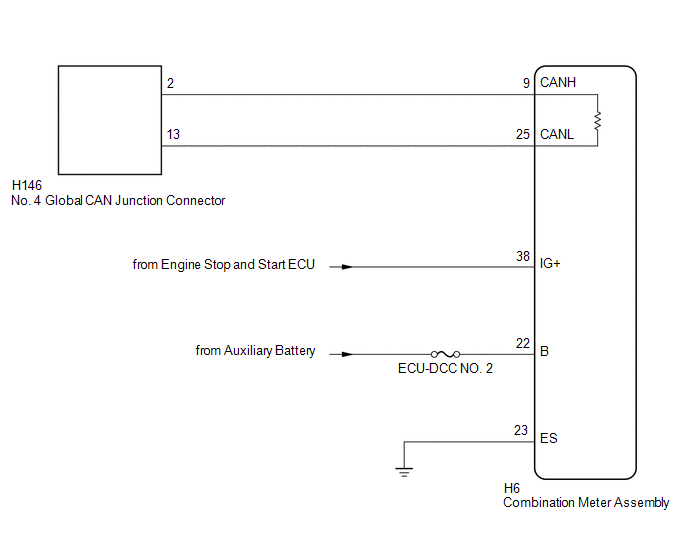
WIRING DIAGRAM
CAUTION / NOTICE / HINT
CAUTION:
When performing the confirmation driving pattern, obey all speed limits and traffic laws.
NOTICE:
-
Because the order of diagnosis is important to allow correct diagnosis, make sure to begin troubleshooting using How to Proceed with Troubleshooting when CAN communication system related DTCs are output.
Click here

- Before measuring the resistance of the CAN bus, turn the ignition switch off and leave the vehicle for 1 minute or more without operating the key or any switches, or opening or closing the doors. After that, disconnect the cable from the negative (-) auxiliary battery terminal and leave the vehicle for 1 minute or more before measuring the resistance.
-
After the ignition switch is turned off, there may be a waiting time before disconnecting the negative (-) auxiliary battery terminal.
Click here

-
When disconnecting and reconnecting the auxiliary battery, there is an automatic learning function that completes learning when the respective system is used.
Click here

-
Some parts must be initialized and set when replacing or removing and installing parts.
Click here

-
After performing repairs, perform the DTC check procedure and confirm that the DTCs are not output again.
DTC check procedure: Turn the ignition switch to ON and wait for 1 minute or more. Then operate the suspected malfunctioning system and drive the vehicle at 60 km/h (37 mph) or more for 5 minutes or more.
-
After the repair, perform the CAN bus check and check that all the ECUs and sensors connected to the CAN communication system are displayed as normal.
Click here

- Inspect the fuses for circuits related to this system before performing the following procedure.
- When replacing the combination meter assembly, always replace it with a new one. If a combination meter assembly which was installed to another vehicle is used, the information stored in it will not match the information from the vehicle and a DTC may be stored.
HINT:
- Before disconnecting related connectors for inspection, push in on each connector body to check that the connector is not loose or disconnected.
- When a connector is disconnected, check that the terminals and connector body are not cracked, deformed or corroded.
PROCEDURE
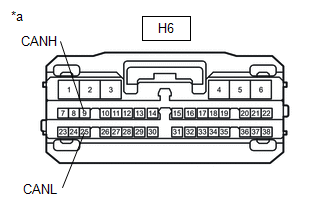
| 1. | CHECK FOR OPEN IN CAN BUS LINES (COMBINATION METER ASSEMBLY MAIN LINE) |
(a) Disconnect the cable from the negative (-) auxiliary battery terminal.
(b) Disconnect the combination meter assembly connector.
| (c) Measure the resistance according to the value(s) in the table below. Standard Resistance:
|
|
| NG |
 | REPAIR OR REPLACE CAN MAIN BUS LINES OR CONNECTOR (COMBINATION METER ASSEMBLY) |
|

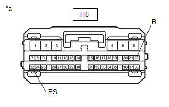
| 2. | CHECK HARNESS AND CONNECTOR (POWER SOURCE CIRCUIT) |
| (a) Measure the resistance according to the value(s) in the table below. Standard Resistance:
|
|
(b) Reconnect the cable to the negative (-) auxiliary battery terminal.
(c) Measure the voltage according to the value(s) in the table below.
Standard Voltage:
| Tester Connection | Condition | Specified Condition |
|---|---|---|
| H6-22 (B) - Body ground | Ignition switch off | 11 to 14 V |
| NG |
 | REPAIR OR REPLACE HARNESS OR CONNECTOR (POWER SOURCE CIRCUIT) |
|

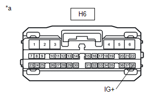
| 3. | CHECK HARNESS AND CONNECTOR (POWER SOURCE CIRCUIT) |
| (a) Measure the voltage according to the value(s) in the table below. Standard Voltage:
|
|
| OK |
 | REPLACE COMBINATION METER ASSEMBLY |
| NG |
 | GO TO STOP AND START SYSTEM (BACKUP BOOST CONVERTER CIRCUIT) |
 Main Body ECU Communication Stop Mode
DESCRIPTION Detection Item Symptom Trouble Area Main Body ECU Communication Stop Mode Communication stop for "Main Body" is indicated on the "Communication Bus Check" screen of the GTS...
 Certification ECU Communication Stop Mode
DESCRIPTION Detection Item Symptom Trouble Area Certification ECU Communication Stop Mode Communication stop for "Certification (Smart) and/or Power Management" is indicated on the "Communication Bus Check" screen of the GTS...
Other information:
Toyota Yaris XP210 (2020-2026) Owner's Manual: Snow Tires
Use snow tires on all four wheels Do not go faster than 75 mph (120 km/h) while driving with snow tires. Inflate snow tires 30 kPa (0.3 kgf/cm2, 4.3 psi) more than recommended on the tire pressure label (driver’s door frame), but never more than the maximum cold-tire pressure shown on the tires...
Toyota Yaris XP210 (2020-2026) Reapir and Service Manual: Stop And Start System Cancel Switch Assembly
ComponentsCOMPONENTS ILLUSTRATION *1 ECO RUN CANCEL SWITCH ASSEMBLY (COMBINATION SWITCH ASSEMBLY) - - RemovalREMOVAL PROCEDURE 1. REMOVE ECO RUN CANCEL SWITCH ASSEMBLY (COMBINATION SWITCH ASSEMBLY) Click here InspectionINSPECTION PROCEDURE 1...
Categories
- Manuals Home
- Toyota Yaris Owners Manual
- Toyota Yaris Service Manual
- Immobilizer System
- Opening and Closing the Liftgate/Trunk Lid
- Headlights
- New on site
- Most important about car
Break-In Period
No special break-in is necessary, but a few precautions in the first 600 miles (1,000 km) may add to the performance, economy, and life of the vehicle.
Do not race the engine. Do not maintain one constant speed, either slow or fast, for a long period of time. Do not drive constantly at full-throttle or high engine rpm for extended periods of time. Avoid unnecessary hard stops. Avoid full-throttle starts.