Toyota Yaris: Can Communication System / Main Body ECU Communication Stop Mode
DESCRIPTION
| Detection Item | Symptom | Trouble Area |
|---|---|---|
| Main Body ECU Communication Stop Mode | Communication stop for "Main Body" is indicated on the "Communication Bus Check" screen of the GTS. Click here
|
|

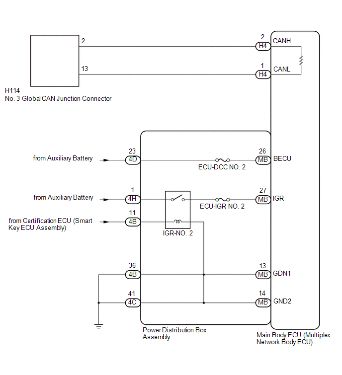
WIRING DIAGRAM
CAUTION / NOTICE / HINT
CAUTION:
When performing the confirmation driving pattern, obey all speed limits and traffic laws.
NOTICE:
-
Because the order of diagnosis is important to allow correct diagnosis, make sure to begin troubleshooting using How to Proceed with Troubleshooting when CAN communication system related DTCs are output.
Click here

- Before measuring the resistance of the CAN bus, turn the ignition switch off and leave the vehicle for 1 minute or more without operating the key or any switches, or opening or closing the doors. After that, disconnect the cable from the negative (-) auxiliary battery terminal and leave the vehicle for 1 minute or more before measuring the resistance.
-
After the ignition switch is turned off, there may be a waiting time before disconnecting the negative (-) auxiliary battery terminal.
Click here

-
When disconnecting and reconnecting the auxiliary battery, there is an automatic learning function that completes learning when the respective system is used.
Click here

-
Some parts must be initialized and set when replacing or removing and installing parts.
Click here

-
After performing repairs, perform the DTC check procedure and confirm that the DTCs are not output again.
DTC check procedure: Turn the ignition switch to ON and wait for 1 minute or more. Then operate the suspected malfunctioning system and drive the vehicle at 60 km/h (37 mph) or more for 5 minutes or more.
-
After the repair, perform the CAN bus check and check that all the ECUs and sensors connected to the CAN communication system are displayed as normal.
Click here

- Inspect the fuses for circuits related to this system before performing the following procedure.
-
Before replacing the main body ECU (multiplex network body ECU), refer to Registration.
Click here

HINT:
- Before disconnecting related connectors for inspection, push in on each connector body to check that the connector is not loose or disconnected.
- When a connector is disconnected, check that the terminals and connector body are not cracked, deformed or corroded.
PROCEDURE
| 1. | CHECK FOR OPEN IN CAN BUS LINES (MAIN BODY ECU (MULTIPLEX NETWORK BODY ECU) MAIN LINE) |
(a) Disconnect the cable from the negative (-) auxiliary battery terminal.
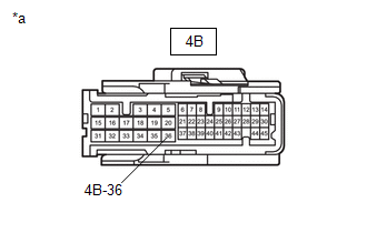
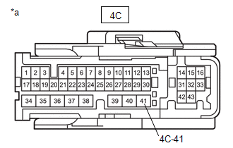
(b) Disconnect the main body ECU (multiplex network body ECU) connector.
| (c) Measure the resistance according to the value(s) in the table below. Standard Resistance:
|
|
| NG |
 | REPAIR OR REPLACE CAN MAIN BUS LINES OR CONNECTOR (MAIN BODY ECU (MULTIPLEX NETWORK BODY ECU)) |
|

| 2. | CHECK HARNESS AND CONNECTOR (POWER SOURCE CIRCUIT) |
(a) Remove the main body ECU (multiplex network body ECU).
Click here

| (b) Measure the resistance according to the value(s) in the table below. Standard Resistance:
NOTICE: Perform this inspection with the wire harness connected to the power distribution box assembly. |
|
(c) Reconnect the cable to the negative (-) auxiliary battery terminal.
(d) Measure the voltage according to the value(s) in the table below.
Standard Voltage:
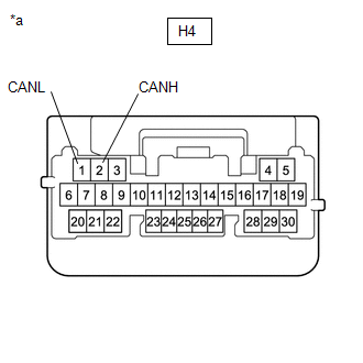
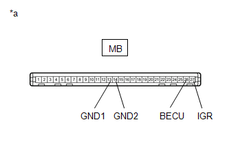
| Tester Connection | Condition | Specified Condition |
|---|---|---|
| MB-26 (BECU) - Body ground | Ignition switch off | 11 to 14 V |
| MB-27 (IGR) - Body ground | Ignition switch ON | 11 to 14 V |
| MB-27 (IGR) - Body ground | Ignition switch off | Below 1 V |
NOTICE:
Perform this inspection with the wire harness connected to the power distribution box assembly.
| Result | Proceed to |
|---|---|
| OK | A |
| NG (BECU) | B |
| NG (IGR) | C |
| NG (GND1) | D |
| NG (GND2) | E |
| A |
 | REPLACE MAIN BODY ECU (MULTIPLEX NETWORK BODY ECU) |
| C |
 | GO TO LIGHTING (INT) SYSTEM (IG SIGNAL CIRCUIT) |
| D |
 | GO TO STEP 4 |
| E |
 | GO TO STEP 5 |
|

| 3. | CHECK HARNESS AND CONNECTOR (BECU SIGNAL CIRCUIT) |
(a) Disconnect the cable from the negative (-) auxiliary battery terminal.
(b) Disconnect the power distribution box assembly connector.
(c) Reconnect the cable to the negative (-) auxiliary battery terminal.
| (d) Measure the voltage according to the value(s) in the table below. Standard Voltage:
|
|
| OK |
 | REPLACE POWER DISTRIBUTION BOX ASSEMBLY |
| NG |
 | REPAIR OR REPLACE HARNESS OR CONNECTOR (BECU SIGNAL CIRCUIT) |
| 4. | CHECK HARNESS AND CONNECTOR (GROUND CIRCUIT) |
(a) Disconnect the cable from the negative (-) auxiliary battery terminal.
(b) Disconnect the power distribution box assembly connector.
| (c) Measure the resistance according to the value(s) in the table below. Standard Resistance:
|
|
| OK |
 | REPLACE POWER DISTRIBUTION BOX ASSEMBLY |
| NG |
 | REPAIR OR REPLACE HARNESS OR CONNECTOR (GROUND CIRCUIT) |
| 5. | CHECK HARNESS AND CONNECTOR (GROUND CIRCUIT) |
(a) Disconnect the cable from the negative (-) auxiliary battery terminal.
(b) Disconnect the power distribution box assembly connector.
| (c) Measure the resistance according to the value(s) in the table below. Standard Resistance:
|
|
| OK |
 | REPLACE POWER DISTRIBUTION BOX ASSEMBLY |
| NG |
 | REPAIR OR REPLACE HARNESS OR CONNECTOR (GROUND CIRCUIT) |
 ECM Communication Stop Mode
DESCRIPTION Detection Item Symptom Trouble Area ECM Communication Stop Mode Communication stop for "ECM (Engine)" is indicated on the "Communication Bus Check" screen of the GTS...
 Combination Meter ECU Communication Stop Mode
DESCRIPTION Detection Item Symptom Trouble Area Combination Meter ECU Communication Stop Mode Communication stop for "Combination Meter" is indicated on the "Communication Bus Check" screen of the GTS...
Other information:
Toyota Yaris XP210 (2020-2026) Reapir and Service Manual: Components
COMPONENTS ILLUSTRATION *1 FRONT SEAT INNER BELT ASSEMBLY *2 RECLINING HINGE COVER *3 RECLINING ADJUSTER RELEASE HANDLE *4 FRONT SEAT CUSHION SHIELD *5 FRONT SEAT INNER CUSHION SHIELD *6 FRONT SEAT BELT ANCHOR PLATE *7 SEPARATE TYPE FRONT SEATBACK COVER - - Tightening torque for "Major areas involving basic vehicle performance such as moving/turning/stopping" : N*m (kgf*cm, ft...
Toyota Yaris XP210 (2020-2026) Reapir and Service Manual: Vehicle Control History
VEHICLE CONTROL HISTORY DESCRIPTION Vehicle Control History is a function that captures and stores ECU data when triggered by specific vehicle behavior. It may be possible to determine the cause of the malfunction by checking the vehicle history information and freeze frame data...
Categories
- Manuals Home
- Toyota Yaris Owners Manual
- Toyota Yaris Service Manual
- To Set Speed
- Key Battery Replacement
- Removal
- New on site
- Most important about car
Fuel Gauge
The fuel gauge shows approximately how much fuel is remaining in the tank when the ignition is switched ON. We recommend keeping the tank over 1/4 full.
