Toyota Yaris: Sfi System / O2 Sensor Circuit Range/Performance Bank 1 Sensor 1 Signal Rate of Change Below Threshold (P2A0026)
DESCRIPTION
Refer to DTC P003012.
Click here

HINT:
Although the DTC titles say oxygen sensor, this DTC relate to the air fuel ratio sensor (sensor 1).
| DTC No. | Detection Item | DTC Detection Condition | Trouble Area | MIL | Note |
|---|---|---|---|---|---|
| P2A0026 | O2 Sensor Circuit Range/Performance Bank 1 Sensor 1 Signal Rate of Change Below Threshold | The calculated value for the air fuel ratio sensor (sensor 1) response rate deterioration level is less than the threshold (2 trip detection logic). |
| Comes on | SAE: P2A00 |
MONITOR DESCRIPTION
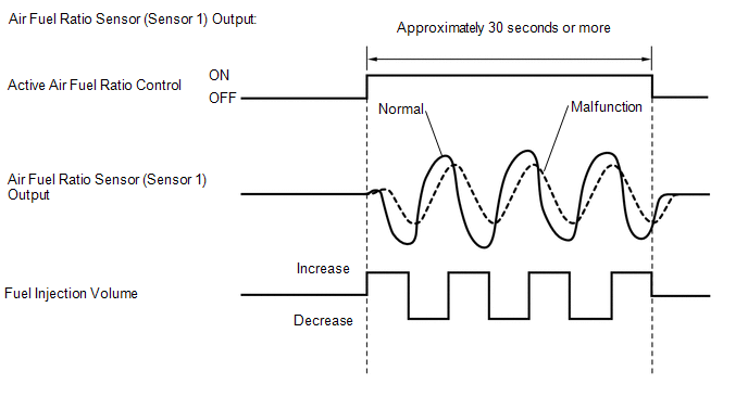
After the engine is warmed up, the ECM performs air fuel ratio feedback control to maintain the air fuel ratio at the stoichiometric level. In addition, active air fuel ratio control is performed for approximately 30 seconds after preconditions are met in order to measure the air fuel ratio sensor (sensor 1) response rate. During active air fuel ratio control, the ECM forcibly increases and decreases the injection volume by a certain amount, based on the stoichiometric air fuel ratio learned during normal air fuel ratio control, and measures the air fuel ratio sensor (sensor 1) response rate. The ECM receives a signal from the air fuel ratio sensor (sensor 1) while performing active air fuel ratio control and uses it to calculate the air fuel ratio sensor (sensor 1) response rate deterioration level.
If the value for the air fuel ratio sensor (sensor 1) response rate deterioration level is less than the threshold, the ECM interprets this as a malfunction and stores the DTC.
MONITOR STRATEGY
| Required Sensors/Components | Air fuel ratio sensor (sensor 1) |
| Frequency of Operation | Once per driving cycle |
TYPICAL ENABLING CONDITIONS
| Active air fuel ratio control | Performing |
| Active air fuel ratio control performed when following conditions met | - |
| Engine coolant temperature | 75°C (167°F) or higher |
| Idling | Off |
| Engine speed | 1000 rpm or more, and less than 3000 rpm |
| Air fuel ratio sensor status | Activated |
| Engine load | 10% or higher, and less than 100% |
| Catalyst monitor | Not yet |
| Mass air flow | 4 gm/sec or more, and less than 16 gm/sec |
CONFIRMATION DRIVING PATTERN
HINT:
Performing this confirmation driving pattern will activate the air fuel ratio sensor response monitor.
- Connect the GTS to the DLC3.
- Turn the ignition switch to ON.
- Turn the GTS on.
- Clear the DTCs (even if no DTCs are stored, perform the clear DTC procedure).
- Turn the ignition switch off and wait for at least 30 seconds.
- Turn the ignition switch to ON.
- Turn the GTS on.
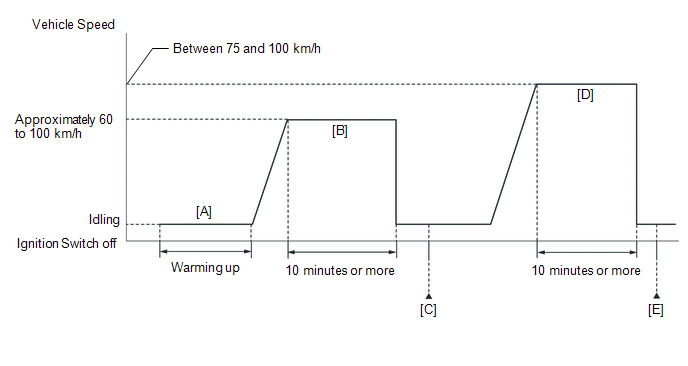
- Start the engine and warm it up until the engine coolant temperature is 75°C (167°F) or higher [A].
-
With the engine running, drive the vehicle at approximately 60 to 100 km/h (37 to 62 mph) for 10 minutes or more in a city area [B].
CAUTION:
When performing the confirmation driving pattern, obey all speed limits and traffic laws.
- Enter the following menus: Powertrain / Engine / Trouble Codes [C].
-
Read the pending DTCs.
HINT:
- If a pending DTC is output, the system is malfunctioning.
- If a pending DTC is not output, perform the following procedure.
- Enter the following menus: Powertrain / Engine / Utility / All Readiness.
- Input the DTC: P2A0026.
-
Check the DTC judgment result.
GTS Display
Description
NORMAL
- DTC judgment completed
- System normal
ABNORMAL
- DTC judgment completed
- System abnormal
INCOMPLETE
- DTC judgment not completed
- Perform driving pattern after confirming DTC enabling conditions
HINT:
- If the judgment result shows NORMAL, the system is normal.
- If the judgment result shows ABNORMAL, the system has a malfunction.
- If the judgment result shows INCOMPLETE and no pending DTC is output, perform the following procedure.
-
With the engine running, drive the vehicle at a speed between 75 and 100 km/h (47 and 62 mph) for 10 minutes [D].
CAUTION:
When performing the confirmation driving pattern, obey all speed limits and traffic laws.
- Enter the following menus: Powertrain / Engine / Trouble Codes [E].
-
Read the pending DTCs.
HINT:
- If a pending DTC is output, the system is malfunctioning.
- If a pending DTC is not output, perform the following procedure.
- Enter the following menus: Powertrain / Engine / Utility / All Readiness.
- Input the DTC: P2A0026.
-
Check the DTC judgment result.
GTS Display
Description
NORMAL
- DTC judgment completed
- System normal
ABNORMAL
- DTC judgment completed
- System abnormal
INCOMPLETE
- DTC judgment not completed
- Perform driving pattern after confirming DTC enabling conditions
HINT:
- If the judgment result shows NORMAL, the system is normal.
- If the judgment result shows ABNORMAL, the system has a malfunction.
- If the judgment result shows INCOMPLETE, drive the vehicle again under an increased load and then recheck the judgment result.
WIRING DIAGRAM
Refer to DTC P003012.
Click here

CAUTION / NOTICE / HINT
NOTICE:
Inspect the fuses for circuits related to this system before performing the following procedure.
HINT:
- DTC P2A0026 may be also stored when the air fuel ratio is stuck at rich or lean.
- A low air fuel ratio sensor (sensor 1) voltage could be caused by a rich air fuel mixture. Check for conditions that would cause the engine to run rich.
- A high air fuel ratio sensor (sensor 1) voltage could be caused by a lean air fuel mixture. Check for conditions that would cause the engine to run lean.
- Sensor 1 refers to the sensor closest to the engine assembly.
- Sensor 2 refers to the sensor farthest away from the engine assembly.
- Read freeze frame data using the GTS. The ECM records vehicle and driving condition information as freeze frame data the moment a DTC is stored. When troubleshooting, freeze frame data can help determine if the vehicle was moving or stationary, if the engine was warmed up or not, if the air fuel ratio was lean or rich, and other data from the time the malfunction occurred.
PROCEDURE
| 1. | CHECK ANY OTHER DTCS OUTPUT (IN ADDITION TO DTC P2A0026) |
(a) Read the DTCs.
Powertrain > Engine > Trouble Codes| Result | Proceed to |
|---|---|
| P2A0026 and other DTCs are output | A |
| P2A0026 is output | B |
HINT:
If any DTCs other than P2A0026 are output, troubleshoot those DTCs first.
| A |
 | GO TO DTC CHART |
|

| 2. | PERFORM ACTIVE TEST USING GTS (CONTROL THE INJECTION VOLUME FOR A/F SENSOR) |
(a) Start the engine and warm it up until the engine coolant temperature reaches 75°C (167°F) or higher.
(b) Warm up the air fuel ratio sensors at an engine speed of 2500 rpm for 90 seconds.
(c) Perform the Control the Injection Volume for A/F Sensor operation with the engine idling.
(d) Monitor the output values of the air fuel ratio sensor (sensor 1) and air fuel ratio sensor (sensor 2) (A/F (O2) Sensor Current B1S1 and A/F (O2) Sensor Current B1S2) displayed on the GTS.
Powertrain > Engine > Active Test| Active Test Display |
|---|
| Control the Injection Volume for A/F Sensor |
| Data List Display |
|---|
| Coolant Temperature |
| Injection Volume |
| A/F (O2) Sensor Current B1S1 |
| A/F (O2) Sensor Current B1S2 |
HINT:
- The Control the Injection Volume for A/F Sensor operation lowers the fuel injection volume by 12.5% or increases the injection volume by 12.5%.
- The air fuel ratio sensor (sensor 1) has an output delay of a few seconds and the air fuel ratio sensor (sensor 2) has a maximum output delay of approximately 20 seconds.
- If the sensor output value does not change (almost no reaction) while performing the Active Test, the sensor may be malfunctioning.
| GTS Display (Sensor) | Injection Volume | Status | Value |
|---|---|---|---|
| A/F (O2) Sensor Current B1S1 (Air fuel ratio (sensor 1)) | 12.5% | Rich | Below -0.075 mA |
| -12.5% | Lean | Higher than 0.037 mA | |
| A/F (O2) Sensor Current B1S2 (Air fuel ratio (sensor 2)) | 12.5% | Rich | Below -0.86 mA |
| -12.5% | Lean | Higher than 0.33 mA |
- Lean: During the Control the Injection Volume for A/F Sensor Active Test, the air fuel ratio sensor (sensor 1) output current (A/F (O2) Sensor Current B1S1) is consistently higher than 0.037 mA, and the air fuel ratio sensor (sensor 2) output current (A/F (O2) Sensor Current B1S2) is consistently higher than 0.33 mA.
- Rich: During the Control the Injection Volume for A/F Sensor Active Test, the air fuel ratio sensor (sensor 1) output current (A/F (O2) Sensor Current B1S1) is consistently below -0.075 mA, and the air fuel ratio sensor (sensor 2) output current (A/F (O2) Sensor Current B1S2) is consistently below -0.86 mA.
- Lean/Rich: During the Control the Injection Volume for A/F Sensor Active Test, the output current of the air fuel ratio sensor (sensor 1) or air fuel ratio sensor (sensor 2) alternate correctly.
HINT:
Refer to "Data List / Active Test" [A/F (O2) Sensor Voltage B1S1, A/F (O2) Sensor Current B1S2.
Click here

| Status of A/F (O2) Sensor Current B1S1 | Status of A/F (O2) Sensor Current B1S2 | Air Fuel Ratio Condition and Air Fuel Ratio Sensor (Sensor 1) Condition | Proceed to |
|---|---|---|---|
| Lean/Rich | Lean/Rich | Normal | A |
| Lean | Lean | Actual air fuel ratio lean | B |
| Rich | Rich | Actual air fuel ratio rich | B |
| Lean | Lean/Rich | Air fuel ratio sensor (sensor 1) malfunction | C |
| Rich | Lean/Rich | Air fuel ratio sensor (sensor 1) malfunction | C |
| B |
 | GO TO STEP 5 |
| C |
 | GO TO STEP 13 |
|

| 3. | CLEAR DTC |
(a) Clear the DTCs.
Powertrain > Engine > Clear DTCs(b) Turn the ignition switch off and wait for at least 30 seconds.
|

| 4. | CHECK WHETHER DTC OUTPUT RECURS (DTC P2A0026) |
(a) Drive the vehicle in accordance with the driving pattern described in the Confirmation Driving Pattern.
(b) Perform the All Readiness.
Powertrain > Engine > Utility| Tester Display |
|---|
| All Readiness |
(c) Input the DTC: P2A0026.
(d) Check the DTC judgment result.
| Result | Proceed to |
|---|---|
| NORMAL (DTCs are not output) | A |
| ABNORMAL (P2A0026 is output) | B |
| A |
 | END |
| B |
 | GO TO STEP 13 |
| 5. | INSPECT AIR FUEL RATIO SENSOR (SENSOR 1) (HEATER RESISTANCE) |
Click here

| NG |
 | REPLACE AIR FUEL RATIO SENSOR (SENSOR 1) |
|

| 6. | CHECK INTAKE SYSTEM |
(a) Check the intake system for vacuum leaks.
Click here

OK:
No leaks in the intake system.
| NG |
 | REPAIR OR REPLACE INTAKE SYSTEM |
|

| 7. | CHECK FOR EXHAUST GAS LEAK |
(a) Check for exhaust gas leaks.
OK:
No gas leaks.
| NG |
 | REPAIR OR REPLACE EXHAUST SYSTEM |
|

| 8. | CHECK FUEL PRESSURE (LOW PRESSURE SIDE) |
Click here

| NG |
 | GO TO STEP 16 |
|

| 9. | READ VALUE USING GTS (FUEL PRESSURE (HIGH)) |
(a) Start the engine and warm it up until the engine coolant temperature is 75°C (167°F) or higher with all the accessories switched off.
(b) Read the Data List when idling.
Powertrain > Engine > Data List| Tester Display |
|---|
| Engine Speed |
| Coolant Temperature |
| Fuel Pressure (High) |
| Injection Mode |
| Result | Proceed to |
|---|---|
| The value of Fuel Pressure (High) is between 3000 kPag and 5000 kPag | A |
| None of the above conditions are met | B |
| B |
 | REPAIR OR REPLACE FUEL SYSTEM (FOR HIGH PRESSURE) |
|

| 10. | READ VALUE USING GTS (FUEL PRESSURE (HIGH)) |
(a) Start the engine and warm it up until the engine coolant temperature is 75°C (167°F) or higher with all the accessories switched off.
(b) Read the Data List at 3000 rpm.
Powertrain > Engine > Data List| Tester Display |
|---|
| Engine Speed |
| Coolant Temperature |
| Fuel Pressure (High) |
| Injection Mode |
| Result | Proceed to |
|---|---|
| The value of Fuel Pressure (High) is between 4000 kPag and 20000 kPag | A |
| None of the above conditions are met | B |
| B |
 | REPAIR OR REPLACE FUEL SYSTEM (FOR HIGH PRESSURE) |
|

| 11. | INSPECT PORT FUEL INJECTOR ASSEMBLY |
(a) Inspect the port fuel injector assembly (whether fuel volume is high or low, and whether injection pattern is poor).
Click here

HINT:
-
Perform "Inspection After Repair" after replacing the port fuel injector assembly.
Click here

| NG |
 | REPLACE PORT FUEL INJECTOR ASSEMBLY |
|

| 12. | INSPECT DIRECT FUEL INJECTOR ASSEMBLY |
Click here

HINT:
-
Perform "Inspection After Repair" after replacing the direct fuel injector assembly.
Click here

| NG |
 | REPLACE DIRECT FUEL INJECTOR ASSEMBLY |
|

| 13. | REPLACE AIR FUEL RATIO SENSOR (SENSOR 1) |
HINT:
Click here

Perform "Inspection After Repair" after replacing the air fuel ratio sensor (sensor 1).
Click here

|

| 14. | CLEAR DTC |
(a) Clear the DTCs.
Powertrain > Engine > Clear DTCs(b) Turn the ignition switch off and wait for at least 30 seconds.
|

| 15. | CHECK WHETHER DTC OUTPUT RECURS (DTC P2A0026) |
(a) Drive the vehicle in accordance with the driving pattern described in the Confirmation Driving Pattern.
(b) Perform the All Readiness.
Powertrain > Engine > Utility| Tester Display |
|---|
| All Readiness |
(c) Input the DTC: P2A0026.
(d) Check the DTC judgment result.
| Result | Proceed to |
|---|---|
| NORMAL (DTCs are not output) | A |
| ABNORMAL (P2A0026 is output) | B |
| A |
 | END |
| B |
 | REPLACE ECM |
| 16. | CHECK FUEL LINE (FOR LOW PRESSURE SIDE) |
(a) Check the fuel lines (for low pressure side) for leaks or blockage.
| OK |
 | GO TO FUEL PUMP CONTROL CIRCUIT |
| NG |
 | REPAIR OR REPLACE FUEL LINE (FOR LOW PRESSURE SIDE) |
 ECM/PCM Engine Off Timer Performance Signal Invalid (P261029)
DESCRIPTION The soak timer operates after the ignition switch is turned off. When a certain amount of time has elapsed after turning the ignition switch off, the soak timer activates the ECM to perform malfunction checks which can only be performed after the engine is stopped...
 Lost Communication with Brake System Control Module Missing Message (U012987)
MONITOR DESCRIPTION The ECM and skid control ECU (brake actuator assembly) send and receive signals via CAN communication. If a communication error occurs between the ECM and skid control ECU (brake actuator assembly), the ECM stores this DTC...
Other information:
Toyota Yaris XP210 (2020-2025) Reapir and Service Manual: Replacement
REPLACEMENT PROCEDURE 1. SEPARATE NO. 1 ENGINE UNDER COVER ASSEMBLY Click here 2. DRAIN ENGINE COOLANT CAUTION: When engine coolant is hot, do not remove the reserve tank cap or the radiator drain cock plug. Fluid and steam may spray out due to high pressure, possibly resulting in burns...
Toyota Yaris XP210 (2020-2025) Reapir and Service Manual: Disassembly
DISASSEMBLY CAUTION / NOTICE / HINT NOTICE: Be sure to read Precaution thoroughly before servicing. Click here Handle components indoors as much as possible to prevent foreign matter from entering and adhering to headlight assembly components...
Categories
- Manuals Home
- Toyota Yaris Owners Manual
- Toyota Yaris Service Manual
- Engine & Hybrid System
- G16e-gts (engine Mechanical)
- Headlights
- New on site
- Most important about car
Front Seat Belt Pretensioners
The front seat belt pretensioners are designed to deploy in moderate or severe frontal, near frontal collisions.
In addition, the pretensioners operate when a side collision or a rollover accident is detected. The pretensioners operate differently depending on what types of air bags are equipped. For more details about the seat belt pretensioner operation, refer to the SRS Air Bag Deployment Criteria.