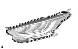
Toyota Yaris: Headlight Assembly / Disassembly
DISASSEMBLY
CAUTION / NOTICE / HINT
NOTICE:
-
Be sure to read Precaution thoroughly before servicing.
Click here
.gif)
- Handle components indoors as much as possible to prevent foreign matter from entering and adhering to headlight assembly components.
- Do not reuse parts which have reduced fastening ability due to thread damage.
- Do not touch the inner surface of the lens and metallic surfaces as much as possible, or they may become dirty.
- Do not allow metallic surfaces to become dirty, as such surfaces become damaged even if they are only lightly wiped with a soft cloth.
- When installing components, make sure that the wire harness is not pinched or pulled.
- Do not use solvent to clean components. Only clean them with a dry cloth.
HINT:
- Use the same procedure for the RH side and LH side.
- The following procedure is for the LH side.
PROCEDURE
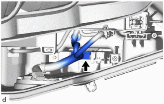
1. REMOVE HEADLIGHT LEVELING MOTOR
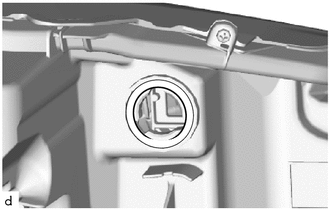
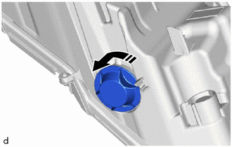
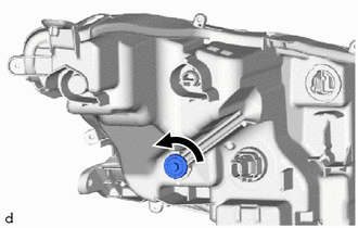
| (a) Turn the aiming screws as shown in the illustration until the aiming screws are disconnected from the headlight unit. HINT: Make sure to remember the number of aiming screw rotations. |
|
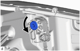
(b) Remove the headlight leveling motor as shown in the illustration.
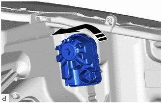
.png) | Remove in this Direction |
2. REMOVE HEADLIGHT LEVELING MOTOR BASE PACKING
| (a) Remove the headlight leveling motor base packing. NOTICE: The headlight leveling motor base packing must not be reused. |
|
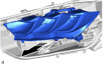
3. REMOVE NO. 1 HEADLIGHT COVER
(a) Remove the No. 1 headlight cover as shown in the illustration.
|
| Remove in this Direction |
4. REMOVE HEADLIGHT LENS SUB-ASSEMBLY
NOTICE:
- Make sure to wear clean rubber gloves when performing this procedure.
- Do not allow dirt or foreign matter to get on the headlight lens sub-assembly.
- Prevention of static electricity is required during this procedure.
- Use static electricity countermeasures SST (desktop anti-static mat set) and observe all precautions to prevent damage to the system by electrostatic discharge (ESD).
- Do not touch the headlight lens sub-assembly with bare hands.
- Do not touch the inner surface of the lens and metallic surfaces as much as possible, or they may become dirty.
- Do not allow metallic surfaces to become dirty, as such surfaces become damaged even if they are only lightly wiped with a soft cloth.
- If there are any fingerprints or foreign matter on the back of the headlight lens sub-assembly, wipe them off with a soft cloth.
- Do not use solvent to clean components. Only clean them with a dry cloth.
SST: 09890-47010
09891-04010
09891-04020
09891-04030
09891-04040
| (a) Disconnect the connector. |
|
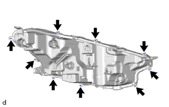
| (b) Remove the 9 screws. |
|
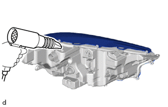
| (c) Using a hair dryer, heat the backside of the headlight assembly. NOTICE: If the headlight assembly is heated unevenly, it will deform or melt. |
|
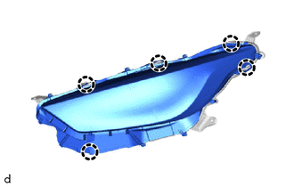
| (d) Disengage the claws to remove the headlight lens sub-assembly. HINT: If the headlight lens sub-assembly cannot be separated even after heating, using a screwdriver with its tip wrapped with protective tape, lift the headlight lens sub-assembly. Be careful not to damage the headlight lens sub-assembly and headlight housing sub-assembly. |
|
5. REMOVE HEADLIGHT LENS GASKET
NOTICE:
- The headlight lens gasket must not be reused.
- Make sure to wear clean rubber gloves when performing this procedure.
- Do not touch the inner surface of the lens and metallic surfaces as much as possible, or they may become dirty.
- Do not allow metallic surfaces to become dirty, as such surfaces become damaged even if they are only lightly wiped with a soft cloth.
- If there are any fingerprints or foreign matter on the headlight unit assembly or other components, wipe them off with a soft cloth.
- Do not use solvent to clean components. Only clean them with a dry cloth.
| (a) Remove the headlight lens gasket from the headlight housing sub-assembly. NOTICE: Make sure to replace the headlight lens gasket with a new one. Failure to do so may cause water ingress. |
|
6. REMOVE LIGHT CONTROL LED ECU
NOTICE:
- Make sure to wear clean rubber gloves when performing this procedure.
- Do not allow dirt or foreign matter to get on the headlight unit or other components.
- Prevention of static electricity is required during this procedure.
- Use static electricity countermeasures SST (desktop anti-static mat set) and observe all precautions to prevent damage to the system by electrostatic discharge (ESD).
- Do not touch the headlight unit with bare hands.
- Do not allow metallic surfaces to become dirty, as such surfaces become damaged even if they are only lightly wiped with a soft cloth.
- If there are any fingerprints or foreign matter on the headlight unit or other components, wipe them off with a soft cloth.
- Do not use solvent to clean components. Only clean them with a dry cloth.
SST: 09890-47010
09891-04010
09891-04020
09891-04030
09891-04040
| (a) Disconnect the connector. |
|
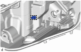
| (b) Remove the screw. |
|
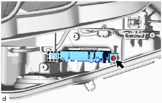
(c) Disengage the guide to remove the light control LED ECU.
7. REMOVE HEADLIGHT UNIT ASSEMBLY
NOTICE:
- Make sure to wear clean rubber gloves when performing this procedure.
- Do not allow dirt or foreign matter to get on the headlight unit or other components.
- Prevention of static electricity is required during this procedure.
- Use static electricity countermeasures SST (desktop anti-static mat set) and observe all precautions to prevent damage to the system by electrostatic discharge (ESD).
- Do not touch the headlight unit with bare hands.
- Do not allow metallic surfaces to become dirty, as such surfaces become damaged even if they are only lightly wiped with a soft cloth.
- If there are any fingerprints or foreign matter on the headlight unit or other components, wipe them off with a soft cloth.
- Do not use solvent to clean components. Only clean them with a dry cloth.
SST: 09890-47010
09891-04010
09891-04020
09891-04030
09891-04040
| (a) Disconnect the connector. |
|
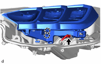
(b) Disengage the claws.
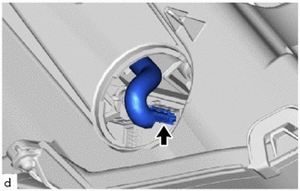
| (c) While holding the headlight unit assembly by hand, turn the aiming screw as shown in the illustration until the aiming screw are disconnected from the headlight unit assembly. HINT: Make sure to remember the number of aiming screw rotations. |
|
(d) Remove the headlight unit assembly from the headlight housing sub-assembly as shown in the illustration.
|
| Remove in this Direction |
(e) When installing a new headlight unit assembly:
| (1) Disengage the clamp to remove the pivot collar. |
|
8. REMOVE HEADLIGHT CORD
(a) Disengage the clamp.
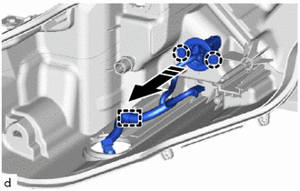
|
| Remove in this Direction |
(b) Disengage the claws to remove the headlight cord.
 Removal
REMOVAL CAUTION / NOTICE / HINT HINT:
Use the same procedure for the RH side and LH side.
The following procedure is for the LH side.
PROCEDURE 1...
 Adjustment
ADJUSTMENT PROCEDURE 1. PREPARE VEHICLE FOR HEADLIGHT AIM ADJUSTMENT (a) Prepare the vehicle:
Ensure that the vehicle body is not damaged or deformed around the headlights...
Other information:
Toyota Yaris XP210 (2020-2026) Reapir and Service Manual: On-vehicle Inspection
ON-VEHICLE INSPECTION PROCEDURE 1. INSPECT CANISTER (FUEL SUCTION PLATE SUB-ASSEMBLY) (for Fuel Tank Cap Method) (a) Inspect evaporative emission control system. Click here (b) Check for clogs in the air filter (when not using the GTS). (1) Start the engine...
Toyota Yaris XP210 (2020-2026) Owner's Manual: Low Speed Pre-Collision System
The Low Speed Pre-Collision System is designed to reduce damage in the event of a collision by operating the brake control (Low Speed Pre-Collision System brake) when the system’s laser sensor detects a vehicle ahead and determines that a collision with a vehicle ahead is unavoidable...
Categories
- Manuals Home
- Toyota Yaris Owners Manual
- Toyota Yaris Service Manual
- Fuse Panel Description
- How to connect USB port/Auxiliary jack
- Adjustment
- New on site
- Most important about car
Supplemental Restraint System (SRS) Precautions
The front and side supplemental restraint systems (SRS) include different types of air bags. Please verify the different types of air bags which are equipped on your vehicle by locating the “SRS AIRBAG” location indicators. These indicators are visible in the area where the air bags are installed.
The air bags are installed in the following locations:
The steering wheel hub (driver air bag) The front passenger dashboard (front passenger air bag) The outboard sides of the front seatbacks (side air bags) The front and rear window pillars, and the roof edge along both sides (curtain air bags)