Toyota Yaris: Sfi System / ECM/PCM Engine Off Timer Performance Signal Invalid (P261029)
DESCRIPTION
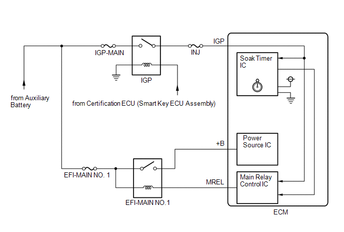
The soak timer operates after the ignition switch is turned off. When a certain amount of time has elapsed after turning the ignition switch off, the soak timer activates the ECM to perform malfunction checks which can only be performed after the engine is stopped. The soak timer is built into the ECM.
| DTC No. | Detection Item | DTC Detection Condition | Trouble Area | MIL | Note |
|---|---|---|---|---|---|
| P261029 | ECM/PCM Engine Off Timer Performance Signal Invalid | ECM internal malfunction (2 trip detection logic) | ECM | Comes on | SAE: P2610 |

MONITOR DESCRIPTION
If the soak timer activates the ECM even though only a short amount of time has elapsed since the ignition switch was turned off, or if the soak timer does not activate the ECM even though a considerable amount of time has elapsed since the ignition switch was turned off, the ECM determines that the soak timer is malfunctioning, illuminates the MIL and stores a DTC the next time the ignition switch is turned to ON.
MONITOR STRATEGY
| Required Sensors/Components | ECM |
| Frequency of Operation | Once per driving cycle |
CONFIRMATION DRIVING PATTERN
- Connect the GTS to the DLC3.
- Turn the ignition switch to ON.
- Turn the GTS on.
- Clear the DTCs (even if no DTCs are stored, perform the clear DTC procedure).
- Turn the ignition switch off and wait for at least 30 seconds.
- Start the engine and warm it up until the engine coolant temperature reaches 75°C (167°F) or higher.
- Turn the ignition switch off and wait for at least 15 seconds.
- Turn the ignition switch to ON.
- Turn the GTS on.
- Enter the following menus: Powertrain / Engine / Trouble Codes.
-
Read the pending DTCs.
HINT:
- If a pending DTC is output, the system is malfunctioning.
- If a pending DTC is not output, perform the following procedure.
- Enter the following menus: Powertrain / Engine / Utility / All Readiness.
- Input the DTC: P261029.
-
Check the DTC judgment result.
GTS Display
Description
NORMAL
- DTC judgment completed
- System normal
ABNORMAL
- DTC judgment completed
- System abnormal
INCOMPLETE
- DTC judgment not completed
- Perform driving pattern after confirming DTC enabling conditions
HINT:
- If the judgment result is NORMAL, the system is normal.
- If the judgment result is ABNORMAL, the system has a malfunction.
CAUTION / NOTICE / HINT
HINT:
- DTC P261029 is set if an internal ECM problem is detected. Diagnostic procedures are not required. ECM replacement is required.
- Read Freeze Frame Data using the GTS. The ECM records vehicle and driving condition information as Freeze Frame Data the moment a DTC is stored. When troubleshooting, Freeze Frame Data can help determine if the vehicle was moving or stationary, if the engine was warmed up or not, if the air fuel ratio was lean or rich, and other data from the time the malfunction occurred.
PROCEDURE
| 1. | REPLACE ECM |
HINT:
Click here

|
| 2. | CLEAR DTC |
(a) Clear the DTCs.
Powertrain > Engine > Clear DTCs(b) Turn the ignition switch off and wait for at least 30 seconds.
|
| 3. | CHECK WHETHER DTC OUTPUT RECURS (DTC P261029) |
(a) Drive the vehicle in accordance with the driving pattern described in Confirmation Driving Pattern.
(b) Read the Pending DTCs.
Powertrain > Engine > Trouble CodesHINT:
If no pending DTC is output, the repair has been successfully completed.
| NEXT |
 | END |
 Turbocharger/Supercharger Bypass Valve "A" Actuator Stuck Closed (P23AA73)
DESCRIPTION Refer to DTC P003312. Click here
DTC No. Detection Item DTC Detection Condition Trouble Area MIL Note P23AA73 Turbocharger/Supercharger Bypass Valve "A" Actuator Stuck Closed Either of the following conditions is met (1 trip detection logic)...
 O2 Sensor Circuit Range/Performance Bank 1 Sensor 1 Signal Rate of Change Below Threshold (P2A0026)
DESCRIPTION Refer to DTC P003012. Click here
HINT: Although the DTC titles say oxygen sensor, this DTC relate to the air fuel ratio sensor (sensor 1)...
Other information:
Toyota Yaris XP210 (2020-2026) Owner's Manual: Engine Coolant
Inspecting Coolant Level Inspect the antifreeze protection and coolant level in the coolant reservoir at least once a year—at the beginning of the winter season—and before traveling where temperatures may drop below freezing. Inspect the condition and connections of all cooling system and heater hoses...
Toyota Yaris XP210 (2020-2026) Reapir and Service Manual: Fail-safe Chart
F..
Categories
- Manuals Home
- Toyota Yaris Owners Manual
- Toyota Yaris Service Manual
- G16e-gts (engine Mechanical)
- Headlights
- Power Integration No.1 System Missing Message (B235287,B235587,B235787-B235987)
- New on site
- Most important about car
Turning the Engine Off
Stop the vehicle completely. Manual transaxle: Shift into neutral and set the parking brake.Automatic transaxle: Shift the selector lever to the P position and set the parking brake.
Press the push button start to turn off the engine. The ignition position is off.

