Toyota Yaris: Sfi System / Turbocharger/Supercharger Bypass Valve "A" Actuator Stuck Closed (P23AA73)
DESCRIPTION
Refer to DTC P003312.
Click here

| DTC No. | Detection Item | DTC Detection Condition | Trouble Area | MIL | Note |
|---|---|---|---|---|---|
| P23AA73 | Turbocharger/Supercharger Bypass Valve "A" Actuator Stuck Closed | Either of the following conditions is met (1 trip detection logic).
|
| - | SAE: P23AA |
MONITOR DESCRIPTION
Air By-pass Valve Assembly Stuck OpenWhen the accelerator pedal is fully released while the vehicle is stopped after engine warm-up, the ECM opens and closes the air by-pass valve assembly and checks the operation.
At that time, if the operating current value when the air by-pass valve assembly is opened differs from the normal state, the ECM judges that the air by-pass valve assembly is stuck open and stores a DTC.
Dual Intake Air Flow Difference MalfunctionWhen the difference between the intake air flow between is the threshold value or more when boosting, the ECM determines that there is a malfunction in the intake and exhaust system and outputs a DTC.
CONFIRMATION DRIVING PATTERN
- Connect the GTS to the DLC3.
- Turn the ignition switch to ON.
- Turn the GTS on.
- Clear the DTCs (even if no DTCs are stored, perform the clear DTC procedure).
- Start the engine and warm it up until the engine coolant temperature reaches 75°C (167°F) or higher.
- Turn the ignition switch off and wait for at least 30 seconds.
- Turn the ignition switch to ON.
- Turn the GTS on.
- Start the engine.
- Idle the engine for 1 minute or more.
- Enter the following menus: Powertrain / Engine / Trouble Codes.
-
Read the pending DTCs.
HINT:
- If a pending DTC is output, the system is malfunctioning.
- If a pending DTC is not output, perform the following procedure.
- Enter the following menus: Powertrain / Engine / Utility / All Readiness.
- Input the DTC: P23AA73.
-
Check the DTC judgment result.
GTS Display
Description
NORMAL
- DTC judgment completed
- System normal
ABNORMAL
- DTC judgment completed
- System abnormal
INCOMPLETE
- DTC judgment not completed
- Perform driving pattern after confirming DTC enabling conditions
HINT:
- If the judgment result is NORMAL, the system is normal.
- If the judgment result is ABNORMAL, the system is malfunctioning.
WIRING DIAGRAM
Refer to DTC P003312.
Click here

CAUTION / NOTICE / HINT
NOTICE:
Inspect the fuses for circuits related to this system before performing the following procedure.
HINT:
Read Freeze Frame Data using the GTS. The ECM records vehicle and driving condition information as Freeze Frame Data the moment a DTC is stored. When troubleshooting, Freeze Frame Data can help determine if the vehicle was moving or stationary, if the engine was warmed up or not, if the air fuel ratio was lean or rich, and other data from the time the malfunction occurred.
PROCEDURE
| 1. | CHECK ANY OTHER DTCS OUTPUT (IN ADDITION TO DTC P23AA73) |
(a) Read the DTCs.
Powertrain > Engine > Trouble Codes| Result | Proceed to |
|---|---|
| P23AA73 is output | A |
| P23AA73 and other DTCs are output | B |
HINT:
If any DTCs other than P23AA73 are output, troubleshoot those DTCs first.
| B |
 | GO TO DTC CHART |
|

| 2. | PERFORM ACTIVE TEST USING GTS (ACTIVATE THE AIR BYPASS VALVE) |
(a) Remove the air by-pass valve assembly.
HINT:
Do not disconnect the connector.
(b) Enter the following menus.
Powertrain > Engine > Active Test| Tester Display |
|---|
| Activate the Air Bypass Valve |
(c) Check that the air by-pass valve assembly moves according to the Active Test.
OK:
Air by-pass valve assembly moves according to the Active Test
| NG |
 | GO TO STEP 5 |
|

| 3. | CLEAR DTC |
(a) Clear the DTCs.
Powertrain > Engine > Clear DTCs(b) Turn the ignition switch off and wait for at least 30 seconds.
|

| 4. | CHECK WHETHER DTC OUTPUT RECURS (P23AA73) |
(a) Drive the vehicle in accordance with the driving pattern described in Confirmation Driving Pattern.
(b) Enter the following menus.
Powertrain > Engine > Utility| Tester Display |
|---|
| All Readiness |
(c) Input the DTC: P23AA73.
(d) Check the DTC judgment result.
| Result | Proceed to |
|---|---|
| NORMAL (DTCs are not output) | A |
| ABNORMAL (P23AA73 is output) | B |
| A |
 | END |
| B |
 | GO TO STEP 5 |
| 5. | INSPECT AIR BY-PASS VALVE ASSEMBLY |
(a) Inspect the air by-pass valve assembly, referring to the On-vehicle Inspection for Air by-pass Valve Assembly.
Click here

(b) Inspect the air by-pass valve assembly, referring to the Inspection for Air by-pass Valve Assembly.
| NG |
 | REPLACE AIR BY-PASS VALVE ASSEMBLY |
|

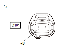
| 6. | CHECK TERMINAL VOLTAGE (POWER SOURCE OF AIR BY-PASS VALVE ASSEMBLY) |
(a) Disconnect the air by-pass valve assembly connector.
(b) Turn the ignition switch to ON.
| (c) Measure the voltage according to the value(s) in the table below. Standard Voltage:
|
|
| NG |
 | GO TO STEP 8 |
|

| 7. | CHECK HARNESS AND CONNECTOR (AIR BY-PASS VALVE ASSEMBLY - ECM) |
(a) Disconnect the air by-pass valve assembly connector.
(b) Disconnect the ECM connector.
(c) Measure the resistance according to the value(s) in the table below.
Standard Resistance:
| Tester Connection | Condition | Specified Condition |
|---|---|---|
| D101-2(ABV) - D104-20(ABV) | Always | Below 1 Ω |
| D101-2(ABV) or D104-20(ABV) - Body ground and other terminals | Always | 10 kΩ or higher |
| OK |
 | REPLACE ECM |
| NG |
 | REPAIR OR REPLACE HARNESS OR CONNECTOR |
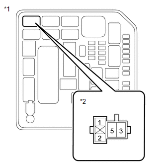
| 8. | INSPECT EFI-MAIN NO. 1 RELAY |
Click here

| NG |
 | REPLACE EFI-MAIN NO. 1 RELAY |
|

| 9. | CHECK HARNESS AND CONNECTOR (POWER SOURCE OF EFI-MAIN NO. 1 RELAY) |
| (a) Remove the EFI-MAIN NO. 1 relay from the No. 1 engine room relay block assembly. |
|
(b) Measure the voltage according to the value(s) in the table below.
Standard Voltage:
| Tester Connection | Condition | Specified Condition |
|---|---|---|
| 3(EFI-MAIN NO. 1 relay) - Body ground | Always | 11 to 14 V |
| NG |
 | REPAIR OR REPLACE HARNESS OR CONNECTOR (AUXILIARY BATTERY - EFI-MAIN NO. 3 RELAY) |
|

| 10. | CHECK HARNESS AND CONNECTOR (EFI-MAIN NO. 1 RELAY - AIR BY-PASS VALVE ASSEMBLY) |
(a) Remove the EFI-MAIN NO. 1 relay, EFI-MAIN NO. 3 relay and EDU relay from the No. 1 engine room relay block assembly.
HINT:
Remove the EFI-MAIN NO. 3 relay and EDU relay connected between the checked terminals as the coil inside the relay influences the measurement value.
(b) Disconnect the air by-pass valve assembly connector.
(c) Measure the resistance according to the value(s) in the table below.
Standard Resistance:
| Tester Connection | Condition | Specified Condition |
|---|---|---|
| 5(EFI-MAIN NO. 1 relay) - D101-1(+B) | Always | Below 1 Ω |
| 5(EFI-MAIN NO. 1 relay) or D101-1(+B) - Body ground and other terminals | Always | 10 kΩ or higher |
| OK |
 | REPAIR OR REPLACE HARNESS OR CONNECTOR (EFI-MAIN NO. 1 RELAY - EFI-MAIN NO. 3 RELAY) |
| NG |
 | REPAIR OR REPLACE HARNESS OR CONNECTOR |
 A/F (O2) Sensor Positive Current Control Bank 1 Sensor 2 Circuit Short to Ground (P22AB11,P22AB12,P22AB13,P22AB16,P22AB17,P22B211,P22B212)
DESCRIPTION Refer to DTC P003612. Click here
DTC No. Detection Item DTC Detection Condition Trouble Area MIL Note P22AB11 A/F (O2) Sensor Positive Current Control Bank 1 Sensor 2 Circuit Short to Ground The A1B+ voltage is 1...
 ECM/PCM Engine Off Timer Performance Signal Invalid (P261029)
DESCRIPTION The soak timer operates after the ignition switch is turned off. When a certain amount of time has elapsed after turning the ignition switch off, the soak timer activates the ECM to perform malfunction checks which can only be performed after the engine is stopped...
Other information:
Toyota Yaris XP210 (2020-2026) Reapir and Service Manual: On-vehicle Inspection
ON-VEHICLE INSPECTION CAUTION / NOTICE / HINT CAUTION: To prevent injury due to contact with an operating V-ribbed belt or cooling fan, keep your hands and clothing away from the V-ribbed belt and cooling fan when working in the engine compartment with the engine running or the ignition switch ON...
Toyota Yaris XP210 (2020-2026) Owner's Manual: Vehicle Data Recordings
Your Toyota is equipped with several sophisticated computers that will record certain data, such as: Engine speed Accelerator status Brake status Vehicle speed Shift position The recorded data varies according to the vehicle grade level and options with which it is equipped...
Categories
- Manuals Home
- Toyota Yaris Owners Manual
- Toyota Yaris Service Manual
- Battery Monitor Module General Electrical Failure (P058A01)
- Fuse Panel Description
- Removal
- New on site
- Most important about car
Supplemental Restraint System (SRS) Precautions
The front and side supplemental restraint systems (SRS) include different types of air bags. Please verify the different types of air bags which are equipped on your vehicle by locating the “SRS AIRBAG” location indicators. These indicators are visible in the area where the air bags are installed.
The air bags are installed in the following locations:
The steering wheel hub (driver air bag) The front passenger dashboard (front passenger air bag) The outboard sides of the front seatbacks (side air bags) The front and rear window pillars, and the roof edge along both sides (curtain air bags)