Toyota Yaris: Sfi System / A/F (O2) Sensor Positive Current Control Bank 1 Sensor 2 Circuit Short to Ground (P22AB11,P22AB12,P22AB13,P22AB16,P22AB17,P22B211,P22B212)
DESCRIPTION
Refer to DTC P003612.
Click here

| DTC No. | Detection Item | DTC Detection Condition | Trouble Area | MIL | Note |
|---|---|---|---|---|---|
| P22AB11 | A/F (O2) Sensor Positive Current Control Bank 1 Sensor 2 Circuit Short to Ground | The A1B+ voltage is 1.43 V or less for 5 seconds or more (2 trip detection logic). |
| Comes on | SAE: P22AC |
| P22AB12 | A/F (O2) Sensor Positive Current Control Bank 1 Sensor 2 Circuit Short to Battery | The A1B+ voltage is higher than 6.135 V for 5 seconds or more (2 trip detection logic). |
| Comes on | SAE: P22AD |
| P22AB13 | A/F (O2) Sensor Positive Current Control Bank 1 Sensor 2 Circuit Open | 100 seconds or more elapse after the air fuel ratio sensor (sensor 2) heater turns on and the air fuel ratio sensor (sensor 2) impedance is higher than 510 Ω (2 trip detection logic). |
| Comes on | SAE: P22AB |
| P22AB16 | A/F (O2) Sensor Positive Current Control Bank 1 Sensor 2 Circuit Voltage Below Threshold | When A1B+ voltage is higher than 2.77 V, the difference between terminals A1B+ and A1B- is 0.2 V or less for 5 seconds or more (2 trip detection logic). |
| Comes on | SAE: P22AC |
| P22AB17 | A/F (O2) Sensor Positive Current Control Bank 1 Sensor 2 Circuit Voltage Above Threshold | Difference between terminals A1B+ and A1B- is higher than 1.72 V for 5 seconds or more (2 trip detection logic). |
| Comes on | SAE: P22AD |
| P22B211 | A/F (O2) Sensor Negative Current Control Bank 1 Sensor 2 Circuit Short to Ground | The A1B- voltage is 1.07 V or less for 5 seconds or more (2 trip detection logic). |
| Comes on | SAE: P22B3 |
| P22B212 | A/F (O2) Sensor Negative Current Control Bank 1 Sensor 2 Circuit Short to Battery | The A1B- voltage is higher than 4.59 V for 5 seconds or more (2 trip detection logic). |
| Comes on | SAE: P22B4 |
MONITOR DESCRIPTION
These DTCs are stored when there is an open or short in the air fuel ratio sensor (sensor 2) circuit, or the air fuel ratio sensor (sensor 2) output value is abnormal. The voltage of the air fuel ratio sensor (sensor 2) is monitored while the ignition switch is ON, or the impedance (impedance is an electrical term that indicates the difficulty of flow of current) is checked while engine running. If the voltage of the air fuel ratio sensor (sensor 2) is outside the normal range, or the impedance is outside the normal range, the ECM illuminates the MIL and stores a DTC.
MONITOR STRATEGY
| Required Sensors/Components | Air fuel ratio sensor (sensor 2) |
| Frequency of Operation | Continuous |
CONFIRMATION DRIVING PATTERN
- Connect the GTS to the DLC3.
- Turn the ignition switch to ON.
- Turn the GTS on.
- Clear the DTCs (even if no DTCs are stored, perform the clear DTC procedure).
- Turn the ignition switch off and wait for at least 30 seconds.
- Start the engine and wait 5 minutes or more.
- Turn the GTS on.
- Enter the following menus: Powertrain / Engine / Trouble Codes.
-
Read the pending DTCs.
HINT:
- If a pending DTC is output, the system is malfunctioning.
- If a pending DTC is not output, perform the following procedure.
- Enter the following menus: Powertrain / Engine / Utility / All Readiness.
- Input the DTC: P22AB11, P22AB12, P22AB13, P22AB16, P22AB17, P22B211 or P22B212.
-
Check the DTC judgment result.
GTS Display
Description
NORMAL
- DTC judgment completed
- System normal
ABNORMAL
- DTC judgment completed
- System abnormal
INCOMPLETE
- DTC judgment not completed
- Perform driving pattern after confirming DTC enabling conditions
HINT:
- If the judgment result is NORMAL, the system is normal.
- If the judgment result is ABNORMAL, the system is malfunctioning.
- If the judgment result is INCOMPLETE, idle the engine for 5 minutes and check the DTC judgment result again.
WIRING DIAGRAM
Refer to DTC P003612.
Click here

CAUTION / NOTICE / HINT
NOTICE:
Inspect the fuses for circuits related to this system before performing the following procedure.
HINT:
-
Refer to "Data List / Active Test" [A/F (O2) Sensor Current B1S2].
Click here

- Read Freeze Frame Data using the GTS. The ECM records vehicle and driving condition information as Freeze Frame Data the moment a DTC is stored. When troubleshooting, Freeze Frame Data can help determine if the vehicle was moving or stationary, if the engine was warmed up or not, if the air fuel ratio was lean or rich, and other data from the time the malfunction occurred.
- Sensor 1 refers to the sensor closest to the engine assembly.
- Sensor 2 refers to the sensor farthest away from the engine assembly.
PROCEDURE
| 1. | CHECK TERMINAL VOLTAGE (AIR FUEL RATIO SENSOR (SENSOR 2) VOLTAGE) |
HINT:
Make sure that the connector is properly connected. If it is not, securely connect it and check for DTCs again.
(a) Disconnect the air fuel ratio sensor (sensor 2) connector.
(b) Turn the ignition switch to ON.
| (c) Measure the voltage according to the value(s) in the table below. Standard Voltage:
|
|
HINT:
Perform "Inspection After Repair" after replacing the air fuel ratio sensor (sensor 2).
Click here

| OK |
 | REPLACE AIR FUEL RATIO SENSOR (SENSOR 2) |
|

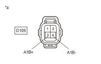
| 2. | CHECK HARNESS AND CONNECTOR (AIR FUEL RATIO SENSOR (SENSOR 2) - ECM) |
(a) Disconnect the air fuel ratio sensor (sensor 2) connector.
(b) Disconnect the ECM connector.
(c) Measure the resistance according to the value(s) in the table below.
Standard Resistance:
| Tester Connection | Condition | Specified Condition |
|---|---|---|
| D109-1(HA1B) - D104-1(HA1B) | Always | Below 1 Ω |
| D109-3(A1B+) - D104-118(A1B+) | Always | Below 1 Ω |
| D109-4(A1B-) - D104-117(A1B-) | Always | Below 1 Ω |
| D109-1(HA1B) or D104-1(HA1B) - Body ground and other terminals | Always | 10 kΩ or higher |
| D109-3(A1B+) or D104-118(A1B+) - Body ground and other terminals | Always | 10 kΩ or higher |
| D109-4(A1B-) or D104-117(A1B-) - Body ground and other terminals | Always | 10 kΩ or higher |
| OK |
 | REPLACE ECM |
| NG |
 | REPAIR OR REPLACE HARNESS OR CONNECTOR |
 A/F (O2) Sensor Signal Biased/Stuck Rich Bank 1 Sensor 2 Circuit Current Below Threshold (P227118)
DESCRIPTION Refer to DTC P003612. Click here
DTC No. Detection Item DTC Detection Condition Trouble Area MIL Note P227118 A/F (O2) Sensor Signal Biased/Stuck Rich Bank 1 Sensor 2 Circuit Current Below Threshold While the fuel-cut operation is performed (during vehicle deceleration), the air fuel ratio sensor (sensor 2) current is less than 7...
 Turbocharger/Supercharger Bypass Valve "A" Actuator Stuck Closed (P23AA73)
DESCRIPTION Refer to DTC P003312. Click here
DTC No. Detection Item DTC Detection Condition Trouble Area MIL Note P23AA73 Turbocharger/Supercharger Bypass Valve "A" Actuator Stuck Closed Either of the following conditions is met (1 trip detection logic)...
Other information:
Toyota Yaris XP210 (2020-2025) Reapir and Service Manual: Components
COMPONENTS ILLUSTRATION *1 REAR SEATBACK ASSEMBLY *2 BENCH TYPE REAR SEAT CUSHION ASSEMBLY *3 REAR SEAT CUSHION LOCK HOOK - - Tightening torque for "Major areas involving basic vehicle performance such as moving/turning/stopping" : N*m (kgf*cm, ft...
Toyota Yaris XP210 (2020-2025) Reapir and Service Manual: Left Front Wheel Speed Sensor Circuit Intermittent (C05001F)
DESCRIPTION The speed sensor detects wheel speed and sends the appropriate signals to the skid control ECU (brake actuator assembly). These signals are used for brake control. Speed sensor rotors have rows of alternating N and S magnetic poles, and their magnetic fields change when the rotors turn...
Categories
- Manuals Home
- Toyota Yaris Owners Manual
- Toyota Yaris Service Manual
- Maintenance
- Opening and Closing the Liftgate/Trunk Lid
- G16e-gts (engine Mechanical)
- New on site
- Most important about car
Break-In Period
No special break-in is necessary, but a few precautions in the first 600 miles (1,000 km) may add to the performance, economy, and life of the vehicle.
Do not race the engine. Do not maintain one constant speed, either slow or fast, for a long period of time. Do not drive constantly at full-throttle or high engine rpm for extended periods of time. Avoid unnecessary hard stops. Avoid full-throttle starts.