Toyota Yaris: Airbag System / Precaution
PRECAUTION
CAUTION:
Failure to carry out service procedures in the correct sequence could cause SRS parts to unexpectedly deploy and possibly lead to serious injuries. Furthermore, if a mistake is made when servicing SRS parts, they may fail to operate when required. Before performing servicing (including installation/removal, inspection and replacement of parts), be sure to read the following precautions.
(a) Before performing service on any of the SRS parts listed below (including installation/removal, inspection and replacement of parts), be sure to read the following precautions, and perform the procedures correctly using the methods described herein.
- Airbag sensor assembly
- Front airbag sensor
- Side airbag pressure sensor
- No. 1 side airbag sensor
- Horn button assembly
- Instrument panel passenger without door airbag assembly
- Curtain shield airbag assembly
- Front seat airbag assembly
- Front seat outer belt assembly
- Airbag cut off switch cylinder sub-assembly
- Passenger airbag ON/OFF indicator (telltale light assembly)
PRECAUTION FOR DISCONNECTING CABLE FROM NEGATIVE AUXILIARY BATTERY TERMINAL
(a) As SRS malfunctions are difficult to confirm, Diagnostic Trouble Codes (DTCs) become the most important source of information when troubleshooting. When troubleshooting the SRS, always check for DTCs before disconnecting the cable from the negative (-) auxiliary battery terminal.
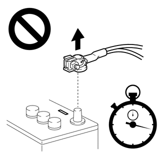
(b) Make sure to turn the ignition switch off before disconnecting the cable from the negative (-) auxiliary battery terminal.
NOTICE:
After turning the ignition switch off, waiting time may be required before disconnecting the cable from the negative (-) auxiliary battery terminal.
Click here

HINT:
When disconnecting and reconnecting the cable to the auxiliary battery terminal, there is an automatic learning function that completes learning when the respective system is used.
Click here

(c) Work must be started at least 60 seconds after the ignition switch is turned off and the cable is disconnected from the negative (-) auxiliary battery terminal.
CAUTION:
The SRS is equipped with a back-up power source. If work is started within 60 seconds of disconnecting the cable from the negative (-) auxiliary battery terminal, the SRS parts may deploy.
(d) When the cable is disconnected from the negative (-) auxiliary battery terminal, the memory of various systems will be cleared. Because of this, be sure to make a record of the contents memorized in each system before starting work. When work is finished, adjust each system to its previous state.
GENERAL PRECAUTION
(a) Information labels are attached to the SRS parts. Follow the instructions on the labels.
(b) Never disassemble or attempt to repair any of the SRS parts.
(c) If any of the SRS parts are dropped, or if any cracks, dents or other defects are found, replace them with new parts.
(d) Never use SRS parts from another vehicle. When replacing parts, use new parts.
(e) Do not expose any of the SRS parts directly to high temperatures or flames.
(f) If the vehicle has been involved in a minor collision where the SRS did not deploy, the SRS parts should be inspected before further use of the vehicle.
(g) Do not apply grease, detergent, oil or water to the SRS parts. If applied, immediately wipe it off with a dry cloth.
(h) When deploying or storing the SRS parts, avoid places with a high temperature and high humidity, and keep them away from electrical noise.
(i) When disposing of the vehicle or an SRS part by itself, deploy it using SST before disposal.
CAUTION:
Dispose of the airbags and pretensioners according to the disposal procedures for each SRS part.
(j) Never measure the resistance of the SRS parts.
CAUTION:
Never measure the resistance of the SRS parts because current from the tester may cause the SRS parts to deploy.
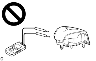
(k) Use a voltmeter/ohmmeter with high impedance (minimum = 10 kΩ) for troubleshooting electrical circuits.
(l) Be sure to check the SRS warning light and multi-information display after checking, removing and installing, or replacing the airbag and sensor.
PRECAUTION FOR AIRBAGS (HORN BUTTON ASSEMBLY, INSTRUMENT PANEL PASSENGER WITHOUT DOOR AIRBAG ASSEMBLY, CURTAIN SHIELD AIRBAG ASSEMBLY AND FRONT SEAT AIRBAG ASSEMBLY)
(a) Keep the deployment side of an airbag facing upward even when the airbag is temporarily removed during service.
CAUTION:
Always place a removed or a new airbag with the deployment side facing upward. Placing the airbag with the deployment side facing downward could cause a serious accident if the airbag deploys.
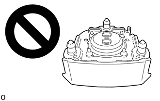
(b) When storing an airbag, do not place anything on top of it or place it in a pile.
PRECAUTION FOR PRETENSIONERS (FRONT SEAT OUTER BELT ASSEMBLY)
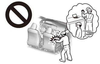
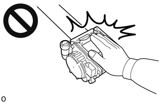
(a) Do not touch the area around the retractor, even when a front seat outer belt assembly or rear seat outer belt assembly is temporarily removed during service.
CAUTION:
If the pretensioner unexpectedly deploys and the front seat outer belt assembly or rear seat outer belt assembly is retracted during an operation, it could cause a serious accident.
(b) When storing a pretensioner, do not place objects on top of it or place it in a pile.
PRECAUTION FOR SPIRAL CABLE SUB-ASSEMBLY
(a) Do not remove/install the spiral cable sub-assembly with the auxiliary battery connected and the ignition switch ON.
(b) Do not rotate the spiral cable sub-assembly without the steering wheel assembly installed, with the auxiliary battery connected and the ignition switch ON.
(c) Ensure that the steering wheel assembly is installed and aligned straight when inspecting the steering sensor.
(d) When rotating the spiral cable sub-assembly, make sure to push on the interlock to release the interlock mechanism.
(e) Removing the steering sensor from the spiral cable sub-assembly without using a lock pin may result in a misaligned center position of the steering sensor. Therefore, make sure to use the lock pin provided with a new spiral cable sub-assembly when removing the steering sensor from the spiral cable sub-assembly.
(f) Be sure that the spiral cable sub-assembly is in the neutral position during installation and when removing and installing the steering wheel assembly.
Click here

NOTICE:
If the steering wheel assembly is turned without the spiral cable sub-assembly installed in the neutral position, the cable may break.
PRECAUTION FOR AIRBAG SENSOR ASSEMBLY AND AIRBAG SENSORS (FRONT AIRBAG SENSOR, SIDE AIRBAG PRESSURE SENSOR AND NO. 1 SIDE AIRBAG SENSOR)
(a) When the SRS parts are deployed (including when only an airbag or pretensioner is deployed) due to a collision, be sure to replace all sensors in the damaged areas (anywhere in need of repair) and the airbag sensor assembly.
(b) Visually check the airbag sensors in undamaged areas for defects.
(1) The defects are as follows:
- Cracks in the sensor housing
- Dents in the sensor housing
- Chips in the sensor housing
- Cracks or other damage to the connector
- Damage to the serial number (except side airbag pressure sensor)
OK:
No defects are found.
If any defects are found or an airbag sensor has detected a major collision, replace the airbag sensor with a new one.
(c) When disconnecting or reconnecting a connector of the airbag sensor assembly, front airbag sensor, side airbag pressure sensor and No. 1 side airbag sensor connectors, make sure to do so with the sensor installed to the vehicle.
(d) If a sensor has been dropped make sure to replace it with a new one.
(e) If a sensor has been subjected to strong impact make sure to replace it with a new one.
(f) Never disassemble any of the SRS parts.
PRECAUTION FOR SIDE AIRBAG PRESSURE SENSOR
(a) Do not make any modifications to the front door that may change the inner pressure of the front door.
(b) Do not allow any foreign matter to enter the side airbag pressure sensor as it may affect the pressure detection performance of the sensor.
(c) When painting the front door, remove or apply protective tape to the side airbag pressure sensor to prevent paint from attaching to it.
(d) Make sure that the parts which maintain the sealing performance of the front door are securely installed. If the sealing performance of the front door decreases, the pressure detection performance of the side airbag pressure sensor may be affected. Repair or replace parts as necessary.
PRECAUTION WHEN REPLACING AIRBAG SENSOR ASSEMBLY
(a) When the airbag sensor assembly is replaced, perform zero point calibration for the yaw rate and acceleration sensor.
Click here

HINT:
The yaw rate and acceleration sensor is built into the airbag sensor assembly.
(b) When the airbag sensor assembly is replaced, update the ECU security key.
Click here

PRECAUTION FOR WIRE HARNESS AND CONNECTOR
(a) All wire harnesses except unexposed harnesses in the engine compartment are colored yellow.
(b) As special connectors are used, be careful when handling them.
HINT:
Refer to How to Connect or Disconnect Airbag Connector.
Click here

WHEN SERVICING DAMAGED VEHICLE
(a) Before using an electric welder on the vehicle, remove any SRS parts around the area being repaired.
(b) Before repairs, remove the airbag sensors/airbag sensor assembly if impacts are likely to be applied to the sensor during repairs.
(c) Never expose an airbag sensor directly to high temperatures.
(d) As the SRS parts are very hot after being deployed, ensure that all wire harnesses and connectors around deployed SRS parts are not damaged.

 Parts Location
PARTS LOCATION ILLUSTRATION
*1 FRONT AIRBAG SENSOR LH *2 FRONT AIRBAG SENSOR RH *3 SIDE AIRBAG PRESSURE SENSOR LH *4 SIDE AIRBAG PRESSURE SENSOR RH *5 NO...
Other information:
Toyota Yaris XP210 (2020-2026) Owner's Manual: DSC OFF Switch
Press the DSC OFF switch to turn off the TCS/DSC. The DSC OFF indicator light in the combination meter will illuminate. Press the switch again to turn the TCS/DSC back on. The DSC OFF indicator light will turn off. When DSC is on and you attempt to free the vehicle when it is stuck, or drive it out of freshly fallen snow, the TCS (part of the DSC system) will activate...
Toyota Yaris XP210 (2020-2026) Reapir and Service Manual: A/F (O2) Sensor Circuit Bank 1 Sensor 2 Circuit Current (Voltage) Below Threshold (P013616)
DESCRIPTION Refer to DTC P003612. Click here DTC No. Detection Item DTC Detection Condition Trouble Area MIL Note P013616 A/F (O2) Sensor Circuit Bank 1 Sensor 2 Circuit Current (Voltage) Below Threshold Either of the following conditions is met (2 trip detection logic)...
Categories
- Manuals Home
- Toyota Yaris Owners Manual
- Toyota Yaris Service Manual
- Engine Start Function When Key Battery is Dead
- Immobilizer System
- Fuel Gauge
- New on site
- Most important about car
Supplemental Restraint System (SRS) Precautions
The front and side supplemental restraint systems (SRS) include different types of air bags. Please verify the different types of air bags which are equipped on your vehicle by locating the “SRS AIRBAG” location indicators. These indicators are visible in the area where the air bags are installed.
The air bags are installed in the following locations:
The steering wheel hub (driver air bag) The front passenger dashboard (front passenger air bag) The outboard sides of the front seatbacks (side air bags) The front and rear window pillars, and the roof edge along both sides (curtain air bags)