Toyota Yaris: Airbag System / Parts Location
PARTS LOCATION
ILLUSTRATION
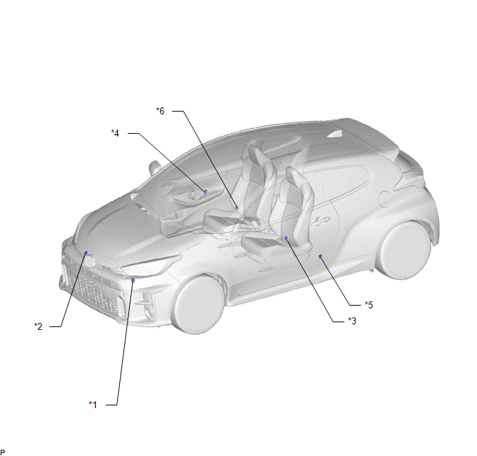
| *1 | FRONT AIRBAG SENSOR LH | *2 | FRONT AIRBAG SENSOR RH |
| *3 | SIDE AIRBAG PRESSURE SENSOR LH | *4 | SIDE AIRBAG PRESSURE SENSOR RH |
| *5 | NO. 1 SIDE AIRBAG SENSOR LH | *6 | NO. 1 SIDE AIRBAG SENSOR RH |
ILLUSTRATION
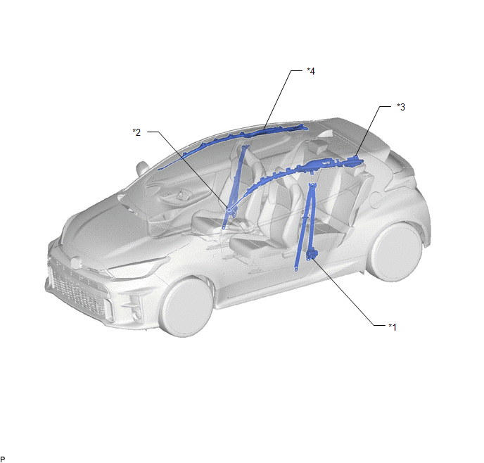
| *1 | FRONT SEAT OUTER BELT ASSEMBLY LH | *2 | FRONT SEAT OUTER BELT ASSEMBLY RH |
| *3 | CURTAIN SHIELD AIRBAG ASSEMBLY LH | *4 | CURTAIN SHIELD AIRBAG ASSEMBLY RH |
ILLUSTRATION
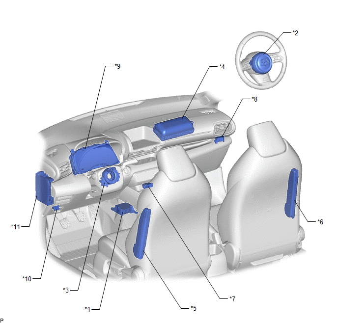
| *1 | AIRBAG SENSOR ASSEMBLY | *2 | HORN BUTTON ASSEMBLY |
| *3 | SPIRAL CABLE SUB-ASSEMBLY | *4 | INSTRUMENT PANEL PASSENGER WITHOUT DOOR AIRBAG ASSEMBLY |
| *5 | FRONT SEAT AIRBAG ASSEMBLY LH | *6 | FRONT SEAT AIRBAG ASSEMBLY RH |
| *7 | TELLTALE LIGHT ASSEMBLY - PASSENGER AIRBAG ON/OFF INDICATOR | *8 | AIRBAG CUT OFF SWITCH CYLINDER SUB-ASSEMBLY |
| *9 | COMBINATION METER ASSEMBLY - SRS WARNING LIGHT | *10 | DLC3 |
| *11 | POWER DISTRIBUTION BOX ASSEMBLY - A/BAG-IGR FUSE - ECU-IGR NO. 2 FUSE | - | - |
 Precaution
PRECAUTION CAUTION: Failure to carry out service procedures in the correct sequence could cause SRS parts to unexpectedly deploy and possibly lead to serious injuries...
 System Diagram
SYSTEM DIAGRAM
Communication Table Transmitting ECU / Parts (Transmitter) Receiving ECU / Parts (Receiver) Signal Communication Method Front Airbag Sensor Airbag Sensor Assembly
Front collision G signal
Direct line No...
Other information:
Toyota Yaris XP210 (2020-2026) Reapir and Service Manual: System Description
SYSTEM DESCRIPTION FRONT WIPER CONTROL FUNCTION Control/Function Description MIST function Operates the front wipers in LO when the front wiper switch is held in the MIST position. Auto operation Operates the wipers as requested by the rain sensor when the front wiper switch is in the AUTO position...
Toyota Yaris XP210 (2020-2026) Reapir and Service Manual: Components
C..
Categories
- Manuals Home
- Toyota Yaris Owners Manual
- Toyota Yaris Service Manual
- G16e-gts (engine Mechanical)
- Power Integration No.1 System Missing Message (B235287,B235587,B235787-B235987)
- How to use USB mode
- New on site
- Most important about car
Turning the Engine Off
Stop the vehicle completely. Manual transaxle: Shift into neutral and set the parking brake.Automatic transaxle: Shift the selector lever to the P position and set the parking brake.
Press the push button start to turn off the engine. The ignition position is off.