Toyota Yaris: Vehicle Stability Control System / Multi-axis Acceleration Sensor Module "A" Supply Voltage Circuit Voltage Out of Range (C14D71C)
DESCRIPTION
The airbag sensor assembly has a built-in yaw rate and acceleration sensor and detects the vehicle condition.
This DTC is stored when the skid control ECU (brake actuator assembly) receives a sensor supply voltage malfunction signal from the acceleration sensor (airbag sensor assembly).
This DTC may be stored due to an intermittent low power source voltage.
| DTC No. | Detection Item | DTC Detection Condition | Trouble Area | DTC Output from |
|---|---|---|---|---|
| C14D71C | Multi-axis Acceleration Sensor Module "A" Supply Voltage Circuit Voltage Out of Range | When the +BS terminal voltage is from 9.5 to 17.4 V at a vehicle speed exceeding 3 km/h (2 mph), an acceleration sensor power source malfunction signal is received for 10 seconds or more. |
| Brake |
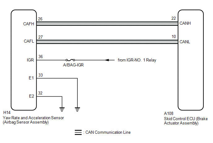
WIRING DIAGRAM
CAUTION / NOTICE / HINT
NOTICE:
- Inspect the fuses for circuits related to this system before performing the following procedure.
-
If the yaw rate and acceleration sensor (airbag sensor assembly) was replaced or reinstalled, perform "Calibration".
Click here

PROCEDURE
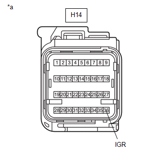
| 1. | CHECK HARNESS AND CONNECTOR (IGR TERMINAL) |
(a) Disconnect the cable from the negative (-) auxiliary battery terminal, and wait for at least 90 seconds.
(b) Make sure that there is no looseness at the locking part and the connecting part of the connectors.
OK:
The connector is securely connected.
| (c) Disconnect the H14 yaw rate and acceleration sensor (airbag sensor assembly) connector. |
|
(d) Check both the connector case and the terminals for deformation and corrosion.
OK:
No deformation or corrosion.
(e) Connect the cable to the negative (-) auxiliary battery terminal.
(f) Turn the ignition switch to ON.
(g) Measure the voltage according to the value(s) in the table below.
Standard Voltage:
| Tester Connection | Condition | Specified Condition |
|---|---|---|
| H14-36 (IGR) - Body ground | Ignition switch ON | 11 to 14 V |
| NG |
 | REPAIR OR REPLACE HARNESS OR CONNECTOR |
|

| 2. | CHECK HARNESS AND CONNECTOR (E1 AND E2 TERMINAL) |
(a) Turn the ignition switch off.
(b) Measure the resistance according to the value(s) in the table below.
Standard Resistance:
| Tester Connection | Condition | Specified Condition |
|---|---|---|
| H14-33 (E1) - Body ground | 1 minute or more after disconnecting the cable from the negative (-) auxiliary battery terminal | Below 1 Ω |
| H14-32 (E2) - Body ground | 1 minute or more after disconnecting the cable from the negative (-) auxiliary battery terminal | Below 1 Ω |
| NG |
 | REPAIR OR REPLACE HARNESS OR CONNECTOR |
|

| 3. | CLEAR DTC |
(a) Reconnect the H14 yaw rate and acceleration sensor (airbag sensor assembly) connector.
(b) Operate the GTS to clear the codes.
Chassis > Brake > Clear DTCs(c) Press the DTC clear button.
(d) Turn the ignition switch off.
|

| 4. | RECONFIRM DTC |
(a) Based on the Freeze Frame Data and interview with the customer, attempt to reproduce the conditions when the malfunction occurred.
(b) Operate the GTS to read the DTCs.
Chassis > Brake > Trouble Codes(c) Check if the same DTC is output.
| Result | Proceed to |
|---|---|
| C14D71C is not output | A |
| C14D71C is output | B |
| A |
 | USE SIMULATION METHOD TO CHECK |
| B |
 | REPLACE AIRBAG SENSOR ASSEMBLY |
 ABS Solenoid Control Module Actuator Stuck On (C143A7E,C143A7F)
DESCRIPTION The ABS solenoid relay is built into the skid control ECU in the brake actuator assembly. The ABS solenoid relay supplies power to the holding solenoid and reduction solenoid...
 Left Front Wheel Speed Sensor Supply Voltage Circuit Short to Ground or Open (C14E014,C14E314)
DESCRIPTION Refer to DTC C05001F. Click here
DTC No. Detection Item DTC Detection Condition Trouble Area DTC Output from C14E014 Left Front Wheel Speed Sensor Supply Voltage Circuit Short to Ground or Open With the +BS terminal voltage 9...
Other information:
Toyota Yaris XP210 (2020-2025) Reapir and Service Manual: Fail-safe Chart
F..
Toyota Yaris XP210 (2020-2025) Reapir and Service Manual: Components
COMPONENTS ILLUSTRATION *1 STEERING WHEEL ASSEMBLY - - Tightening torque for "Major areas involving basic vehicle performance such as moving/turning/stopping" : N*m (kgf*cm, ft.*lbf) - - ILLUSTRATION *1 LOWER STEERING COLUMN COVER *2 TURN SIGNAL SWITCH ASSEMBLY WITH SPIRAL CABLE SUB-ASSEMBLY *3 UPPER STEERING COLUMN COVER - - ILLUSTRATION *1 FRONT DOOR SCUFF PLATE LH *2 COWL SIDE TRIM BOARD LH *3 NO...
Categories
- Manuals Home
- Toyota Yaris Owners Manual
- Toyota Yaris Service Manual
- Auto Lock/Unlock Function
- Power Integration No.1 System Missing Message (B235287,B235587,B235787-B235987)
- Opening and Closing the Liftgate/Trunk Lid
- New on site
- Most important about car
Supplemental Restraint System (SRS) Precautions
The front and side supplemental restraint systems (SRS) include different types of air bags. Please verify the different types of air bags which are equipped on your vehicle by locating the “SRS AIRBAG” location indicators. These indicators are visible in the area where the air bags are installed.
The air bags are installed in the following locations:
The steering wheel hub (driver air bag) The front passenger dashboard (front passenger air bag) The outboard sides of the front seatbacks (side air bags) The front and rear window pillars, and the roof edge along both sides (curtain air bags)