Toyota Yaris: Vehicle Stability Control System / ABS Solenoid Control Module Actuator Stuck On (C143A7E,C143A7F)
DESCRIPTION
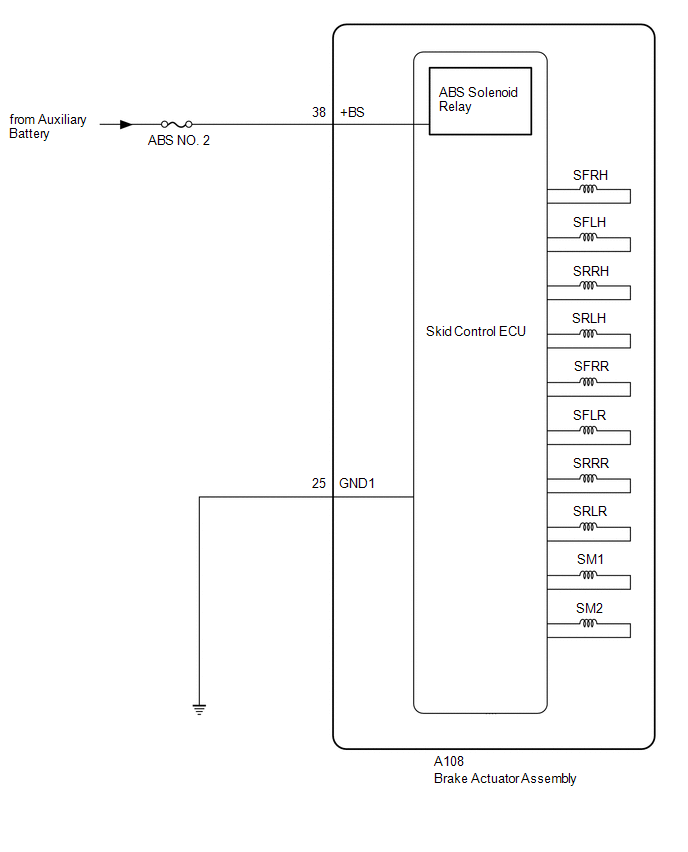
The ABS solenoid relay is built into the skid control ECU in the brake actuator assembly.
The ABS solenoid relay supplies power to the holding solenoid and reduction solenoid.
The solenoid relay is turned on 1.5 seconds after the ignition switch is turned to ON, and is turned off if an open or short in the solenoid is detected by self-diagnosis performed when the vehicle is starting off.
| DTC No. | Detection Item | DTC Detection Condition | Trouble Area | DTC Output from |
|---|---|---|---|---|
| C143A7E | ABS Solenoid Control Module Actuator Stuck On | When voltage at terminal +BS is 9.5 V or higher, solenoid relay is OFF, relay contact is ON continuously for 4.5 seconds or more. | Skid control ECU (brake actuator assembly) | Brake |
| C143A7F | ABS Solenoid Control Module Actuator Stuck Off | When voltage at terminal +BS is 9.5 V or higher and solenoid relay is ON, relay contact is OFF continuously for 0.22 seconds or more. |
| Brake |
WIRING DIAGRAM
CAUTION / NOTICE / HINT
NOTICE:
- Inspect the fuses for circuits related to this system before performing the following procedure.
-
After replacing the skid control ECU (brake actuator assembly), perform "Calibration".
Click here

HINT:
When C137BA2 and/or C137BA3 is output together with C143A7E and/or C143A7F, inspect and repair the trouble areas indicated by C137BA2 and/or C137BA3 first.
for C137BA2: Click here

for C137BA3: Click here

PROCEDURE
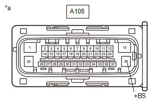
| 1. | CHECK HARNESS AND CONNECTOR (+BS TERMINAL) |
(a) Make sure that there is no looseness at the locking part and the connecting part of the connectors.
OK:
The connector is securely connected.
| (b) Disconnect the A108 skid control ECU (brake actuator assembly) connector. |
|
(c) Check both the connector case and the terminals for deformation and corrosion.
OK:
No deformation or corrosion.
(d) Measure the voltage according to the value(s) in the table below.
Standard Voltage:
| Tester Connection | Condition | Specified Condition |
|---|---|---|
| A108-38 (+BS) - Body ground | Always | 11 to 14 V |
| NG |
 | REPAIR OR REPLACE HARNESS OR CONNECTOR |
|

| 2. | CHECK HARNESS AND CONNECTOR (GND1 TERMINAL) |
(a) Measure the resistance according to the value(s) in the table below.
Standard Resistance:
| Tester Connection | Condition | Specified Condition |
|---|---|---|
| A108-25 (GND1) - Body ground | 1 minute or more after disconnecting the cable from the negative (-) auxiliary battery terminal | Below 1 Ω |
| NG |
 | REPAIR OR REPLACE HARNESS OR CONNECTOR |
|

| 3. | CLEAR DTC |
(a) Reconnect the A108 skid control ECU (brake actuator assembly) connector.
(b) Operate the GTS to clear the codes.
Chassis > Brake > Clear DTCs(c) Press the DTC clear button.
(d) Turn the ignition switch off.
|

| 4. | RECONFIRM DTC |
(a) Based on the Freeze Frame Data and interview with the customer, attempt to reproduce the conditions when the malfunction occurred.
(b) Operate the GTS to read the DTCs.
Chassis > Brake > Trouble Codes(c) Check if the same DTC is output.
| Result | Proceed to |
|---|---|
| C143A7E and C143A7F are not output | A |
| C143A7E or C173A7F is output | B |
HINT:
- If a speed signal of 20 km/h (12 mph) or more is input to the skid control ECU (brake actuator assembly) with the ignition switch ON and the stop light switch assembly off, the ECU performs self-diagnosis of the solenoid circuit.
- If the normal system code is output (no DTCs are output), slightly jiggle the connectors, wire harnesses, and fuses of the skid control ECU (brake actuator assembly).
- If any DTCs are output while jiggling a connector or wire harness of the skid control ECU (brake actuator assembly), inspect and repair the connector or wire harness.
- If no DTCs were output when reconfirming DTCs, checking for intermittent problems is necessary because it is suspected that the original DTCs were stored due to the poor connection of a connector terminal.
| A |
 | USE SIMULATION METHOD TO CHECK |
| B |
 | REPLACE BRAKE ACTUATOR ASSEMBLY |
 ABS Pump Motor Actuator Stuck (C142771)
DESCRIPTION DTC No. Detection Item DTC Detection Condition Trouble Area DTC Output from C142771 ABS Pump Motor Actuator Stuck Actuator pump motor does not operate properly...
 Multi-axis Acceleration Sensor Module "A" Supply Voltage Circuit Voltage Out of Range (C14D71C)
DESCRIPTION The airbag sensor assembly has a built-in yaw rate and acceleration sensor and detects the vehicle condition. This DTC is stored when the skid control ECU (brake actuator assembly) receives a sensor supply voltage malfunction signal from the acceleration sensor (airbag sensor assembly)...
Other information:
Toyota Yaris XP210 (2020-2026) Owner's Manual: Drive Selection
Drive Selection (Automatic Transaxle) Drive selection is a system to switch the vehicle’s drive mode. When the sport mode is selected, vehicle’s response against accelerator operation is enhanced. This provides additional quick acceleration which may be needed to safely make maneuvers such as lane changes, merging onto free ways, or passing other vehicles...
Toyota Yaris XP210 (2020-2026) Reapir and Service Manual: IG Circuit Short to Ground (B227111)
DESCRIPTION This DTC is stored when a malfunction in the IG circuit or IG hold circuit of the certification ECU (smart key ECU assembly) is detected. DTC No. Detection Item DTC Detection Condition Trouble Area Note B227111 IG Circuit Short to Ground When either of the following conditions is met (1-trip detection logic*1): The IG circuit of the certification ECU (smart key ECU assembly) is malfunctioning...
Categories
- Manuals Home
- Toyota Yaris Owners Manual
- Toyota Yaris Service Manual
- Immobilizer System
- Power Integration No.1 System Missing Message (B235287,B235587,B235787-B235987)
- Fuse Panel Description
- New on site
- Most important about car
Break-In Period
No special break-in is necessary, but a few precautions in the first 600 miles (1,000 km) may add to the performance, economy, and life of the vehicle.
Do not race the engine. Do not maintain one constant speed, either slow or fast, for a long period of time. Do not drive constantly at full-throttle or high engine rpm for extended periods of time. Avoid unnecessary hard stops. Avoid full-throttle starts.