Toyota Yaris: Wiper Ecu / Removal
REMOVAL
CAUTION / NOTICE / HINT
HINT:
When the cable is disconnected/reconnected to the battery terminal, systems temporarily stop operating. However, each system has a function that completes learning the first time the system is used.
-
Learning completes when vehicle is driven
Effect/Inoperative Function When Necessary Procedures are not Performed
Necessary Procedures
Link
Lane tracing assist system
Drive the vehicle straight ahead at 35 km/h (22 mph) or more for 5 second or more.
.gif)
Pre-collision system
Stop and start system
Drive the vehicle until stop and start control is permitted (approximately 5 to 60 minutes)
-
Learning completes when vehicle is operated normally
Effect/Inoperative Function When Necessary Procedures are not Performed
Necessary Procedures
Link
Power door lock control system
- Back door opener
Perform door unlock operation with door control switch or electrical key transmitter sub-assembly switch.
Air conditioning system
After the ignition switch is turned to ON, the servo motor standard position is recognized.
-
PROCEDURE
1. PRECAUTION
NOTICE:
After the ignition switch is turned off, there may be a waiting time before disconnecting the negative (-) auxiliary battery terminal.
Click here
2. DISCONNECT CABLE FROM NEGATIVE AUXILIARY BATTERY TERMINAL
Click here
3. REMOVE LOWER INSTRUMENT PANEL FINISH PANEL ASSEMBLY
Click here
4. REMOVE NO. 3 INSTRUMENT PANEL TO COWL BRACE SUB-ASSEMBLY
Click here
5. REMOVE POWER DISTRIBUTION BOX ASSEMBLY WITH MULTIPLEX NETWORK BODY ECU
Click here
6. REMOVE WINDSHIELD WIPER RELAY ASSEMBLY
| (a) Disconnect the 2 connectors. |
|
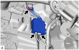
(b) Remove the bolt.
(c) Disengage the guide to remove the windshield wiper relay assembly.
 Components
COMPONENTS ILLUSTRATION
*1 WINDSHIELD WIPER RELAY ASSEMBLY *2 POWER DISTRIBUTION BOX ASSEMBLY WITH MULTIPLEX NETWORK BODY ECU *3 NO. 3 INSTRUMENT PANEL TO COWL BRACE SUB-ASSEMBLY - -
N*m (kgf*cm, ft...
 Installation
INSTALLATION PROCEDURE 1. INSTALL WINDSHIELD WIPER RELAY ASSEMBLY (a) Engage the guides to install the windshield wiper relay assembly.
(b) Install the bolt...
Other information:
Toyota Yaris XP210 (2020-2026) Reapir and Service Manual: Dtc Check / Clear
DTC CHECK / CLEAR CHECK DTC (a) Check for DTCs (Test Failed / Pending / Confirmed). Body Electrical > Pre-Collision System > Trouble Codes GTS Display Description Test Failed Represent malfunctions that were detected during the current trip...
Toyota Yaris XP210 (2020-2026) Reapir and Service Manual: Customize Parameters
CUSTOMIZE PARAMETERS INSTALL CUSTOMIZE THEFT DETERRENT SYSTEM HINT: The following items can be customized. NOTICE: When the customer requests a change in a function, first make sure that the function can be customized. Be sure to make a note of the current settings before customizing...
Categories
- Manuals Home
- Toyota Yaris Owners Manual
- Toyota Yaris Service Manual
- Fuse Panel Description
- Removal
- Brake System Control Module "A" System Voltage System Voltage Low (C137BA2)
- New on site
- Most important about car
Fuel-Filler Lid and Cap
WARNING
When removing the fuel-filler cap, loosen the cap slightly and wait for any hissing to stop, then remove it
Fuel spray is dangerous. Fuel can burn skin and eyes and cause illness if ingested. Fuel spray is released when there is pressure in the fuel tank and the fuel-filler cap is removed too quickly.