Toyota Yaris: Dynamic Radar Cruise Control System / Terminals Of Ecu
TERMINALS OF ECU
CHECK ECM
HINT:
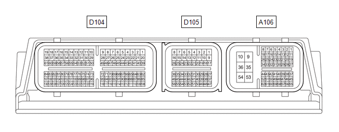
The standard voltage, resistance and waveform between each pair of the ECM terminals is shown in the table below. The appropriate conditions for checking each pair of the terminals are also indicated. The result of checks should be compared with the standard voltage, resistance and waveform for each pair of the terminals as displayed in the Specified Condition column. The illustration above can be used as a reference to identify the ECM terminal locations.
| Terminal No. (Symbol) | Terminal Description | Condition | Specified Condition |
|---|---|---|---|
| A106-21 (STP) - A106-10 (E1) | Stop light switch assembly signal | Brake pedal depressed | 7.5 to 14 V |
| Brake pedal released | 0 to 1.5 V | ||
| A106-22(ST1-) - A106-10(E1) | Stop light switch assembly signal (opposite to STP terminal) | Ignition switch ON, brake pedal depressed | 0 to 1.5 V |
| Ignition switch ON, brake pedal released | 7.5 to 14 V | ||
| A106-27 (CCS) - A106-28 (ECCS) | Steering pad switch circuit | Cruise control switch not pushed | 1 MΩ or higher |
| Cruise control main switch pushed | Below 2.5 Ω | ||
| CANCEL switch pushed | 228 to 252 Ω | ||
| +RES switch pushed | 599 to 661 Ω | ||
| -SET switch pushed | 1463 to 1617 Ω |
NOTICE:
- Turning the ignition switch to ON with connectors disconnected may cause DTCs to be stored. Make sure to clear the DTCs after inspection has been performed.
- Do not apply excessive force to the millimeter wave radar sensor assembly connector.

CHECK MILLIMETER WAVE RADAR SENSOR ASSEMBLY
(a) Measure the voltage and resistance according to the value(s) in the table below.
| Terminal No. (Symbol) | Terminal Description | Condition | Specified Condition |
|---|---|---|---|
| B8-8 (IGB) - B8-1 (SGND) | Power source | Ignition switch ON | 10.5 to 16 V |
| Ignition switch off | Below 1 V | ||
| B8-1 (SGND) - Body ground | Ground | Always | Below 1 Ω |
NOTICE:
- Turning the ignition switch ON with connectors disconnected may cause DTCs to be stored. Make sure to clear the DTCs after inspection has been performed.
- Do not apply excessive force to the forward recognition camera connector.
CHECK FORWARD RECOGNITION CAMERA

(a) Measure the voltage and resistance according to the value(s) in the table below.
| Terminal No. (Symbol) | Terminal Description | Condition | Specified Condition |
|---|---|---|---|
| V10-3 (LKSW) - V10-10 (GND) | Steering pad switch assembly signal (distance control signal) | Ignition switch ON, steering pad switch assembly (vehicle-to-vehicle distance control switch) on | Below 1 V |
| Ignition switch ON, steering pad switch assembly (vehicle-to-vehicle distance control switch) off | 4.75 to 5.25 V | ||
| V10-10 (GND) - Body ground | Ground | Always | Below 1 Ω |
| V10-7 (IGB) - V10-10 (GND) | Power source | Ignition switch ON | 11 to 14 V |
| Ignition switch off | Below 1 V |
 Problem Symptoms Table
PROBLEM SYMPTOMS TABLE NOTICE:
Before replacing the ECM, refer to Service Bulletin.
When replacing the millimeter wave radar sensor assembly, always replace it with a new one...
 Diagnosis System
DIAGNOSIS SYSTEM DIAGNOSIS FUNCTION (a) The diagnosis function turns off the cruise control indicator and displays a warning message when a malfunction is detected...
Other information:
Toyota Yaris XP210 (2020-2026) Owner's Manual: To Set Speed
Activate the cruise control system by pressing the ON switch. The cruise main indication (white) is displayed. Accelerate to the desired speed, which must be more than 16 mph (25 km/h). Set the cruise control by pressing the SET/- switch at the desired speed...
Toyota Yaris XP210 (2020-2026) Reapir and Service Manual: Engine Oil Pressure Too Low (P052400)
DESCRIPTION Refer to DTC P052012 DTC No. Detection Item DTC Detection Condition Trouble Area MIL Note P052400 Engine Oil Pressure Too Low When the engine is running, the oil pressure value output from the engine oil pressure and temperature sensor is less than the target value (1 trip detection logic)...
Categories
- Manuals Home
- Toyota Yaris Owners Manual
- Toyota Yaris Service Manual
- Immobilizer System
- Key Battery Replacement
- Fuse Panel Description
- New on site
- Most important about car
Supplemental Restraint System (SRS) Precautions
The front and side supplemental restraint systems (SRS) include different types of air bags. Please verify the different types of air bags which are equipped on your vehicle by locating the “SRS AIRBAG” location indicators. These indicators are visible in the area where the air bags are installed.
The air bags are installed in the following locations:
The steering wheel hub (driver air bag) The front passenger dashboard (front passenger air bag) The outboard sides of the front seatbacks (side air bags) The front and rear window pillars, and the roof edge along both sides (curtain air bags)